They need an example - turn a screwdriver into molten slag with a 1KVA
😀 .
OS
That is why you use 300 amp screwdriver when working on big amps. Just like this guy at the sears store...😛
Attachments

That is why you use 300 amp screwdriver when working on big amps. Just like this guy at the sears store...😛
Wow, cool! The end must be sharpened so that you can adjust the bias with it 😀
Hi guys, sorry I've been out of discussion for some time 😉 Those business trips...
You're right, R20 and 28 set the trip point, defining the reference level for comparators.
Trip temperature needs to be tested and probably adjusted. I don't think it's going to trip frequently, but as a "last resort"... for situation when all offset and current levels are still OK, but it's getting hot - good thing to have 😉
Do you see any problem using a common reference for both halves of the comparator? I'm trying to reduce the component count anywhere I can.
Here's a modification you might want to do to your board OS. The transformer outputs are in series. One rail is just feeding a voltage detector. The transformer will run cooler if you cut the trace between the secondaries and parallel them. You probably won't have any problems but with the extra relay for a tube transformer it's pretty much maxing out one secondary winding.
Attachments

Do you see any problem using a common reference for both halves of the comparator? I'm trying to reduce the component count anywhere I can.
Sure, they can use a common reference. Sensor transistors may have slightly different characteristics, but we don't need very high accuracy here.
I'm trying to reduce the component count anywhere I can.
Start with C12/13/15/17 , just 2 - 47uF NPO's will do here. At the present size
of the specified 100u@35V, they won't fit (there's one on the processor 5v supply
for reference).
The 47u NPO between the C12/13 +'s and the C15/17 +'s will fit.
OS
Start with C12/13/15/17 , just 2 - 47uF NPO's will do here. At the present size
of the specified 100u@35V, they won't fit (there's one on the processor 5v supply
for reference).
The 47u NPO between the C12/13 +'s and the C15/17 +'s will fit.
OS
I'm going to follow them with a DIP or SMT bridge package instead of all those 1N4148s too. Next I need to figure out how to eliminate Q6 and 30 through the ULN2003 without an AND gate. There's 3 drivers unused in it.
Valery , I don't have either the 35v 100's or the 47u NP's.
Would R26/34 =100K+ and 22uf caps for C12/13/15/17 affect the time constant
of the DC detect , or is the processor set to detect DC under a specific Fc ?
OS
Would R26/34 =100K+ and 22uf caps for C12/13/15/17 affect the time constant
of the DC detect , or is the processor set to detect DC under a specific Fc ?
OS
Did I send the caps for the supply section? A 2200 and two 1000s? I thought I put them in the bag with all the resistors. There was a mess of parts in that box though. I guess I could have easily missed a few.
Valery , I don't have either the 35v 100's or the 47u NP's.
Would R26/34 =100K+ and 22uf caps for C12/13/15/17 affect the time constant
of the DC detect , or is the processor set to detect DC under a specific Fc ?
OS
Hi OS, yes - 100K and 22uF will be fine. This time constant (2-2.5s) is a good practical compromise for eliminating unwanted triggering from the low frequency signal on one hand and fast enough triggering in case of trouble on the other hand.
Did I send the caps for the supply section? A 2200 and two 1000s? I thought I put them in the bag with all the resistors. There was a mess of parts in that box though. I guess I could have easily missed a few.
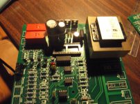
Oh , I already stuffed those (below). The big cap (2200u@35V) was so big it
trespassed on the 1000u/35 (C5) "spot" ... that's why I have them strapped together.
OS
Attachments
Oh , I already stuffed those (below). The big cap (2200u@35V) was so big it
trespassed on the 1000u/35 (C5) "spot" ... that's why I have them strapped together.
OS
Yes they are a bit of a squeeze.
You might want to mount your 7812 regulator under the board on the aluminum plate. It runs pretty hot.
Hi OS, yes - 100K and 22uF will be fine. This time constant (2-2.5s) is a good practical compromise for eliminating unwanted triggering from the low frequency signal on one hand and fast enough triggering in case of trouble on the other hand.
Hi Val. 🙂 What joy of revisiting all my old analog sensor "blocks".
??? - The AC sense , only have 270K for R8/R9.
Q9 should have enough beta to pull it's collector down with the slight higher Z input ?
OS
Yes they are a bit of a squeeze.
You might want to mount your 7812 regulator under the board on the aluminum plate. It runs pretty hot.
What if I just mounted a heatsink made of flashing across all 4 to-220's.
Actually, the 2 lm78xx regs have a tabbed grounds -good . Dang ! that poor 7812 is
running all those "monster" OMRON relays - big flashing from corner screw to corner screw !! 😱
PS - you run the "monsters" right from the ULN2003 ? Does IT get hot at 158ma
X 2 (both omrons)? 😱
OS
The regulator should probably be chassis mounted. It puts out a lot of heat. It's running near the upper end of it's current handling with everything on and it's a steady load so it doesn't get a chance to cool.
ULN2003 is rated maximum 500mA/Darlington. Great device. Doesn't really warm up much at all.
ULN2003 is rated maximum 500mA/Darlington. Great device. Doesn't really warm up much at all.
160ma x2 for the omrons , 21ma x 2 for the shracks (orange relay) +just 10ma
loss through the transistors/IC. 400ma /5w = maxed out for no heatsink.
TI recommends a 10C/w for >5w load. - the chassis or my mounting plate would be
<2-3C/w.
Looks like I'll have to add an inch to my mounting plate. The 7812 leads would also
be too short to make the change (under the board).
The 5V reg should run cool. Only the micro/sensors run on the 5V bus , and the tip's
just have minimal loss - all cool.
OS
Did I send extra regulators? If not I'll send some with the plate. The only warm parts I had were the LM7812 and the transformer. I actually melted one transformer but that was with 3 of the big Omrons on and trying to get everything to start through a bulb limiter while I was messing with those Symasuis.
Did I send extra regulators? If not I'll send some with the plate. The only warm parts I had were the LM7812 and the transformer. I actually melted one transformer but that was with 3 of the big Omrons on and trying to get everything to start through a bulb limiter while I was messing with those Symasuis.
Only <800mA with one sec. /1.6A with paralleled secondaries.
I'll PM you with what's missing and plate dimensions.
This was harder than the spooky's , I actually did the NANO itself with a"wedge"
iron tip - but better than your average soldering (below -nearly stuffed).
PS- I'm only going to use F1 , I have a more robust fuse for the main trafo -
on that back "AC only" plate.
OS
Attachments

- Home
- Amplifiers
- Solid State
- How to build a 21st century protection board