This is all crap. Normal protection circuits work just fine and dandy. Why do you need to involve a microprocessor?
Just because you CAN do something doesn't mean you SHOULD do it!
Just because you CAN do something doesn't mean you SHOULD do it!
This is all crap. Normal protection circuits work just fine and dandy. Why do you need to involve a microprocessor?
Just because you CAN do something doesn't mean you SHOULD do it!
You should think out of the box.
If we got a microcontroller we can put more options on our system like:
Protection on the microcontroler;
Timer to power up, without using that resistor-bridge-capacitor scheme;
Remote control of volume could be a thing, we can integrate a bluetooth module that with a app on Android or iOS we can control a knob on our phone/tablet;
There is a hundred of things we can put on our product or diy design with microcontrollers.
Regards,
Felipe
This is all crap. Normal protection circuits work just fine and dandy. Why do you need to involve a microprocessor?
Just because you CAN do something doesn't mean you SHOULD do it!
Hi Gopher,
Looks like you didn't read through the thread.
The question is - what do you call "normal protection circuits" and what exactly soft-start and protection functions they perform.
It's all about requirements and how to fulfill them.
For my purposes most of the "normal" ones are simply not good enough. Especially for high-power hybrids.
Again, we are talking not only about protection here. This is a control board.
Cheers,
Valery
Why not Arduino instead of PIC?
So better and faster for getting new program on it.
We do use Arduino Nano board.
This is all crap. Normal protection circuits work just fine and dandy. Why do you need to involve a microprocessor?
Just because you CAN do something doesn't mean you SHOULD do it!
The main reason for the arduino is to start everything up in the right order at the right time in a hybrid amplifier. It's there, why not use it? I agree with vzaichenko's approach of doing each protection operation standalone, then feed info to the arduino. Redundant speaker protection and fail safe designs add safety as well. It works very nicely so far and is a very simple add on to almost any amplifier.
Last edited:
You should think out of the box.
If we got a microcontroller we can put more options on our system like:
Protection on the microcontroler;
Timer to power up, without using that resistor-bridge-capacitor scheme;
Remote control of volume could be a thing, we can integrate a bluetooth module that with a app on Android or iOS we can control a knob on our phone/tablet;
There is a hundred of things we can put on our product or diy design with microcontrollers.
Regards,
Felipe
The volume controls and interface might be easier done with an app like Rune player running on a separate standalone unit like a Raspberry pi or Beaglebone. I keep coming back to the idea of datalogging on my bench supply. This could be offloaded to one of those units as well.
In focusing on the AC control of the power supply, which is better, a Triac controller Opto Iso with built in zero crossing connected to the Arduino or separate zero crossing detector circuit and the Arduino directly controlling the Triac? If anyone has an example, please post it. Thanks
Hi,
Attached it is a drawing showing the zero crossing that I used to control my amplifier power ON/OFF. The circuit give you a pulse every 1/2 cycle. Also the Omron Triac relay that I used. It is non zero crossing relay. Used 5 volts to fire it. The zero crossing it is at the bottom left of the drawing.
Attached it is a drawing showing the zero crossing that I used to control my amplifier power ON/OFF. The circuit give you a pulse every 1/2 cycle. Also the Omron Triac relay that I used. It is non zero crossing relay. Used 5 volts to fire it. The zero crossing it is at the bottom left of the drawing.
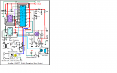
Hi,
Attached it is a clean drawing one.
Is the connection to the triac relay correct in this schematic? It's connected to VSS on the microcontroller.
Hi,
Yes, you are right. When I cleaned the drawing I didn't notice where was connected. Any way you can connect it to any pin in the micro. This was an example. Also attached it is an update drawing with the pin connected to the right pin in the micro. Sorry for the overlooked.
Yes, you are right. When I cleaned the drawing I didn't notice where was connected. Any way you can connect it to any pin in the micro. This was an example. Also attached it is an update drawing with the pin connected to the right pin in the micro. Sorry for the overlooked.
Attachments
Thank you Tauro, this is pretty cool.
Long time ago, I was testing a new 1.5KW transformer at home, connecting it directly to the mains from time to time for measurements, until the building protection disconnected the whole floor (4 apartments) 🙂 Just happened connecting it in a "wrong" moment 😛
I would still leave some inrush resistor though - zero crossing helps to ease the trafo initial start, however we still have some bulk capacitance to charge...
Do you feel it's worth the extra complexity? It's a neat idea but I personally think your chassis mount power resistor is pretty fool proof.
Do you feel it's worth the extra complexity? It's a neat idea but I personally think your chassis mount power resistor is pretty fool proof.
It actually is a pretty fool proof. High-power resistor for 2-3 seconds - works very good.
But as a potential solution for enormously high-power PSU - good to have it in a "toolset" 😉
Hi,
I do ramped the AC on power ON/OFF using the micro and the zero crossing. By doing so the AC will come slowly up/down. Like your are adjusting the AC slowly with a Variac. I has been do it for about 3 years and implemented it in all my amplifiers built. Also it will prevent the inrush current on power ON.
I do ramped the AC on power ON/OFF using the micro and the zero crossing. By doing so the AC will come slowly up/down. Like your are adjusting the AC slowly with a Variac. I has been do it for about 3 years and implemented it in all my amplifiers built. Also it will prevent the inrush current on power ON.
Hi,
Yes, I used for it for the Vcc to the micro. The micro control everything in the amplifier. It read the power switch and turn ON/OFF the amplifier. The micro it is powered all the time.
Yes, I used for it for the Vcc to the micro. The micro control everything in the amplifier. It read the power switch and turn ON/OFF the amplifier. The micro it is powered all the time.
Thank you Tauro, this is pretty cool.
Long time ago, I was testing a new 1.5KW transformer at home, connecting it directly to the mains from time to time for measurements, until the building protection disconnected the whole floor (4 apartments) 🙂 Just happened connecting it in a "wrong" moment 😛
I would still leave some inrush resistor though - zero crossing helps to ease the trafo initial start, however we still have some bulk capacitance to charge...
My previous 800va Genesis trafo's would blink the lights on a 15A 120v
circuit. They would trip the breaker if a coffee pot or other appliance was using
the same circuit.
Former member {MJL21193} and me used the same 12-15A NTC thermistors
to bring inrush under control. He even JUST used a 1R 15A NTC (without
any relay). We both ended up using 15A NTC plus a 2 second relay timed off
the DC rails.
Whats neat , the NTC would actually limit AC current during a rail short.
BTW - I used the 20 year old Genesis (used) NTC's , they survived and
worked great for decades.
-Would your protection circuit have an issue with the NTC's (they save a lot of space and cost only $ 2-3USD).
B57364S209M EPCOS | Mouser
OS
Hi,
Just to clarified. I do not enable the traic at zero crossing permanently. I fired the traic from 90 degree of the AC sine wave and keep increment the firing in small steps until it reach 45 degree then I enable the traic permanently. I do the firing in both positive and negative side of the AC sine wave. I other word it look like ramping the AC by slowly moving the variac knob up or like using a dimmer to turn the light bulb dimmer or brighter. By doing so it prevent the inrush current on power ON and allowed the capacitors to slowly charge. This is a good application for tubes amplifier. It will allow to filament to slowly heat up while the high voltage also slowly increase. Also will eliminate the filament stress at power ON. This is my theory and do not know if it is true since I do not have a tube amplifier. Maybe the members with expertise in tubes will or can collaborate it. My knowledge in tubes are vague.
Just to clarified. I do not enable the traic at zero crossing permanently. I fired the traic from 90 degree of the AC sine wave and keep increment the firing in small steps until it reach 45 degree then I enable the traic permanently. I do the firing in both positive and negative side of the AC sine wave. I other word it look like ramping the AC by slowly moving the variac knob up or like using a dimmer to turn the light bulb dimmer or brighter. By doing so it prevent the inrush current on power ON and allowed the capacitors to slowly charge. This is a good application for tubes amplifier. It will allow to filament to slowly heat up while the high voltage also slowly increase. Also will eliminate the filament stress at power ON. This is my theory and do not know if it is true since I do not have a tube amplifier. Maybe the members with expertise in tubes will or can collaborate it. My knowledge in tubes are vague.
- Home
- Amplifiers
- Solid State
- How to build a 21st century protection board