Here is an amplifier with bootstrapping to show how it works.Yes, i have seen you have divided the Resistance but why..??
Boot strap is used for high input impedance...
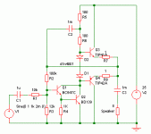
To get high output voltage, the base of Q3 must be raised to a high voltage and current must flow into the base of Q3. All of the current going into Q3's base and the diodes must come through R6.
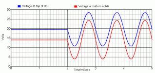
Because there is current flowing through R6, the voltage at the bottom of R6 is lower than the voltage at the top of R6. So, to raise the voltage on Q3's base close to the supply voltage (+25V), the voltage at the top of R6 must be higher than the supply voltage.
C2 makes this possible. When the voltage at the base of Q3 goes up, the voltage at the output also goes up. Because of the capacitor, the voltage at the top of R6 also goes up.
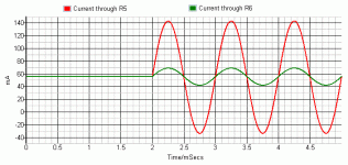
Without the bootstrap capacitor, the current though R6 will change a lot, depending on the output voltage. When the output voltage is high and Q3 needs the most base current, the current through R6 will be very low.
With the capacitor, the current through R6 stays high, even when the output voltage is high.
The change in current through R5 is quite high, but this is OK because this AC signal current is mostly provided by the output transistors, through the bootstrap capacitor.
The AC signal current through R6 is smaller with the bootstrap capacitor. This is good because it means Q1 and Q2 have to give less (AC) output signal current.
So you are right, the bootstrap capacitor increases the input impedance of the output stage, so it is easier to drive for the input stage.
Attachments
Try Wikipedia "diode modelling".
You use diodes in your circuits. Surely it is a good idea for you to know what they do?I have seen, what the use of it in amplifiers...??
If you already understand how diode current changes with voltage and temperature, that is good.
Hi RR
Now you are getting somewhere. In your last post (83) you have a double bootstrap. This keeps the diode currents flowing so they should not become cut-off. But, you have pretty low base resistors now -25 ohms - which means that the current in the diodes is going to be almost 100 mA. You are going to run into trouble because they have a maximum forward current of 75 mA. Also, the voltage across them is going to be around 1V which will cause the output transistor currents to be rather high.
Let's back up a bit. You have chosen FZT849/BCW68 output transistors. These are SOT23 or maybe SOT223 devices which means they aren't going to be able to dissipate much power. However, this is in the right direction. Let's choose instead the ZTX649/ZTX749 transistors which have a gain of 100 at 1A and can dissipate 1W, but can also be mounted on a small aluminium plate for additional heat sinking.
The base drive you need for 625 mA output should be about 6 mA, say. Double this to give a good margin makes 12 mA. With 4.5v across a resistor, the value will be 360 ohms. You can therefore safely use your original 100 ohms for all your base resistors which totals 200 ohms per side but increases the current to 20 mA or so. You could choose to use 150 ohm resistors or run 20 mA and allow for lower gain transistors.
You still have the problem of a high forward voltage across your diodes. Did you check the current flowing in your output transistors? You can only reduce this current by choosing a lower current in the bias resistors (back to 12 mA) or using a different (larger) diodes such as 1N4002 (or if the forward voltage is too large, still, 3 or 6 A power diodes which, although might work, is quite a silly solution as they are more expensive) or adding emitter resistors, which you should do as omitting them is a really bad idea. For an 8 ohm load you could use 1 ohm resistors, or with better control (lower diode voltage) you might consider using 0.47 ohms.
The next problem you have is in driving this output stage, now we have it almost under control. With a double bootstrap you still need to run the driver stage at the same current (12 mA or more) but if you connect the driver collector to the base of the PNP you can cut out one of these currents and only have one 12 (or 20 mA) current path instead of two.
And if you do this you can eliminate the diodes and use a transistor bias generator to set the quiescent current.
Happy learning.
John
Long Tail Pair
Take a look at elliot sound products project 3a you should be able to understand from there how to use a long tail pair. Just google project 3a.
Hello,
I am trying to make an amplifier ( using transistor) of 5watt ( near by this) for this a long tail pair is required in many circuits...
I have seen many link but i don't understand its biasing.😕
Please tell how to make it.??
Thanks
Take a look at elliot sound products project 3a you should be able to understand from there how to use a long tail pair. Just google project 3a.
Last edited:
You can either use a resistor or a constant current source.
An LTP usually passes a couple of milliamps.
An LTP usually passes a couple of milliamps.
- Status
- Not open for further replies.