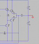
It looks like you forgot to connect the ground to the power supply.here i have stimulated the schematic i don't undewrstand why it is showing output in m volts??
See the red below.
Attachments
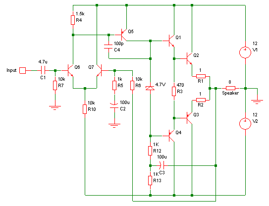
Good questions! Let's start with the capacitors.In this circuit what is the use of C4 and C2, and what will happen if we will not use this long (diff.) pair in amplifier ??
C2 is to reduce DC offset at the output. Transistors are not perfect so there may be a small difference between the base-emitter voltages of Q6 and Q7. Also, the current we need through Q6 to turn on Q5 may not be exactly half of the current through R10. There are also small DC voltage drops across R6 and R7 due to the base currents of Q6 and Q7, which may not be the same. For these reasons, there is a small DC voltage at the input of the amplifier, between the bases of Q6 and Q7.
C2 rolls off the frequency response of the amplifier below about 2Hz, so at DC the gain is one and the DC at the output is the same as at the input. Without C2, DC at the output would be higher.
Some people prefer to leave out C2. With careful design, DC offset can be low enough without it, especially if matched parts are used. Another approach is to put a trimmer potentiometer somewhere in the circuit that allows you to set the DC offset to zero.
~~~~~~~~~~~~~~~~~~~~~~~~~~~~~~~~~~~~~~~~~~~
C4 is for stability, to prevent oscillation at high frequencies. The problem is that the signal is delayed as it goes through the amplifier from input to output.
At some high frequency (probably a couple of MHz), the phase shift reaches 180 degrees, the feedback from output to input through R6 becomes positive instead of negative, and the amplifier oscillates at that frequency.
C4 prevents that by rolling off the gain at high frequencies to make sure the loop gain is less than one before the phase shift reaches 180 degrees.
~~~~~~~~~~~~~~~~~~~~~~~~~~~~~~~~~~~~~~~~~~
BTW: For my simulation, I used BC547C for Q6 and Q7 because they have nice high current gain. Q2 and Q3 each dissipate about 10 watts so they need to be some kind of power transistor. I tried fast ones (Ft=30MHz) and slow ones (Ft=4MHz) and the circuit worked fine both ways.

Last edited:
You actually built the circuit on a PCB or just sim? I find stability relies also on circuit layout construction which may lead to the need for base stoppers, or other local damping circuits.
 I find stability relies also on circuit layout construction which may lead to the need for base stoppers, or other local damping circuits.
The biaising zener has a value that is too high , quiescent current
through the power devices will be at least 1 A , thus each power
device will dissipate 12W , wich seems high for a circuit meant
to experiment in real life.
A 2.7V or 3V zener should be more adequate.
through the power devices will be at least 1 A , thus each power
device will dissipate 12W , wich seems high for a circuit meant
to experiment in real life.
A 2.7V or 3V zener should be more adequate.
@CBS: Just a sim. Agreed about the real-world issues for an actual build.
I was actually pleasantly surprised how well-behaved it is (in the sim😀), since it wasn't intended as an assault on the high-end, but just a "simplest possible" circuit to illustrate how LTPs work.
~~~~~~~~~~~~~~~~~~~~~~~~~~~~~~~~
@Wahab: I chose class A as an easy way to get low distortion from a simple circuit. It also avoids the complication of adjustable bias. For experimenting in real life one could certainly use less bias current as you suggested.
Last edited:
You can make an amplifier without a long tailed pair. One way is to apply the input voltage to the base of the input transistor, and apply the feedback to the emitter of the same transistor. If you do that, there is a DC voltage difference between input and output, so you have to be careful not to get a large DC voltage across the loudspeaker....and what will happen if we will not use this long (diff.) pair in amplifier ??
The easy way to do this is to connect the loudspeaker with a large coupling capacitor and use a single-ended power supply. There used to be lots of amplifiers like this e.g. the Quad 303, but it's not very popular today.
Here's an example circuit, similar to the previous one but with a single input transistor.
Attachments
You can make an amplifier without a long tailed pair. One way is to apply the input voltage to the base of the input transistor, and apply the feedback to the emitter of the same transistor. If you do that, there is a DC voltage difference between input and output, so you have to be careful not to get a large DC voltage across the loudspeaker.
By making without L.P. will overall gain, or distortion will effects or not??
I was just calculating its power like this....
at 8ohms there was 4.5V at one side and with 600mA so, i think it overall power is 2.7Watt. or i have to multiply both by root(2) for RMS value??
at 8ohms there was 4.5V at one side and with 600mA so, i think it overall power is 2.7Watt. or i have to multiply both by root(2) for RMS value??
I was just calculating its power like this....
at 8ohms there was 4.5V at one side and with 600mA so, i think it overall power is 2.7Watt. or i have to multiply both by root(2) for RMS value??
Why, BC547 not 2N3904? andwhat about other transistor..??
you are using very high freq. for stimulation as i am using 3Khz...,why?
at 8ohms there was 4.5V at one side and with 600mA so, i think it overall power is 2.7Watt. or i have to multiply both by root(2) for RMS value??
BTW: For my simulation, I used BC547C for Q6 and Q7 because they have nice high current gain. Q2 and Q3 each dissipate about 10 watts so they need to be some kind of power transistor. I tried fast ones (Ft=30MHz) and slow ones (Ft=4MHz) and the circuit worked fine both ways.
Why, BC547 not 2N3904? andwhat about other transistor..??
you are using very high freq. for stimulation as i am using 3Khz...,why?
No. Gain is set by the feedback resistors, R6 and R5.By making without L.P. will overall gain, or distortion will effects or not??
Distortion is determined by circuit details, can be better or worse.
For voltage or current, RMS value = peak value multiplied by root(1/2).I was just calculating its power like this....
at 8ohms there was 4.5V at one side and with 600mA so, i think it overall power is 2.7Watt. or i have to multiply both by root(2) for RMS value??
So for 5 watts:
9V peak = 6.36V RMS
9V peak / 8 ohms = 1.125A peak
1.125A peak = 0.795A RMS
9V * 1.125A = 10.125 watts peak
6.36V * 0.795A = 5.0625 watts RMS
You can use other transistors but BC547C is good because it has high current gain.Why, BC547 not 2N3904? andwhat about other transistor..??
Look at the datasheets: BC547, 2N3904
BC547C: hFE = 420 to 800
2N3904: hFE = 70 to 300
No. I am simulating at 1KHz and at 20 KHz.you are using very high freq. for stimulation as i am using 3Khz...,why?
The Transition Frequency of the output transistors is 4MHz or 30MHz.
I am not simulating at those frequencies.
or sinewave Vrms = Vpk / sqrt(2)For voltage or current, RMS value = peak value multiplied by root(1/2).
The Transition Frequency of the output transistors is 4MHz or 30MHz.
What is diff. in transition freq...??
and if we talk about the Transistor connected C.C. and others transistor at output of what no.??
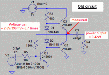
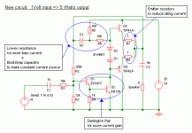
Here's how to make it better and get 5 Watts output.I have used transistor as switch ( saturation and Cutoff Region) many times.
Transistor in active mode (active mode) i have doubt as i am newbie please provide a starting schematic.........
this was y first amplifier.
Attachments
Transistor current gain reduces at high frequencies. The "transition frequency" is the frequency at which the current gain = one.What is diff. in transition freq...??
I don't understand this.😕and if we talk about the Transistor connected C.C. and others transistor at output of what no.??
I don't understand this.😕
Sorry, I just wrote in hurry.
I just want to know the no. of Transistor.
Input transistors were BC547C (NPN) for the first circuit, and BC557C (PNP) for the second circuit.
For output transistors, I first tried MJ15024 (NPN) with MJ15025 (PNP) and NJL3281 (NPN) with NJL1302 (PNP). These are big power transistors, though. You can use smaller ones, so I tried TIP41 (NPN) with TIP42 (PNP) as well. All of these worked OK.
For the other transistors, I just used 2N2222 (NPN) and 2N2904 (PNP). Maybe others would be a bit better. Those are what my simulator uses by default and I didn't bother to change them because I didn't think it was very important. 😱
In the latest circuit in post 34, Q2 is BD139 because the power dissipation is too high for 2N2222.
As you can see in my .62watt amplifiers it is using two Diode as Vbe multipliers for thermal runway...
when i remove these diode the output is distorted, on stimulating i came to know there are working as rectifiers for Q2 base, is this right??
when i remove these diode the output is distorted, on stimulating i came to know there are working as rectifiers for Q2 base, is this right??
Hi RR
I think you can use 2N3055/MJ2955. I've said often that they are not as bad as they are sometimes made out to be. I measured the frequency where the gain reduced 3dB using devices from ST and ON semi: both were around 50 kHz or more, (this is the "fhfe" point not fT where the gain goes to 1) which is fine for simple amplifiers. In fact some of the better amps I've made use these.
You can use MJE3055T and MJE2955T if you don't want too much power (say up to about 20W) which are in TO-220 cases. Or if you want convenience you could use these for higher power in parallel pairs. But I suspect they are not the same chip as the metal can types, because the second breakdown on the metal can devices starts at 40V whereas the TO-220 plastic second breakdown starts at a miserly 35V.
The reputation of the 2N3055 got somewhat tarnished because of the low frequency response of the original device, the old RCA hometaxial base transistor, even though many good amps were made with it (Quad303 etc), but some of the tarnish has been removed with the newer epi base types.
John
- Status
- Not open for further replies.
- Home
- Amplifiers
- Solid State
- How to bias Long tail pair....??


