Hi RR
Take another look at your second circuit in post #56. Resistors R2 and R3 are 100 ohms, and the driver transistor has to work hard to drive current into them. The driver transistor has a 500 ohm load, so the voltage you can get across the bases of the output transistors is only a tenth of the voltage that the driver transistor COULD drive, if you let it, but it can't because of the 100 ohm loads.
You need to let the driver transistor collector be able to swing up and down by the full supply voltage i.e. between 0 (or as close as it can get) and the supply (Vcc). In your circuit you have used a classic 4-resistor biased transistor amplifier for the driver, and a separate output stage without thinking about how the two can be joined up, and optimised for the task you want to do.
The emitter resistor of the driver (500 ohms) will stop the collector reaching zero and the 100 ohm base resistors stops the output voltage swing being very high.
Think of the driver transistor as a variable resistor which you should use instead of R3 and you may begin to understand how to design a simple Class B amplifier.
John
Hi again,
and i have seeen when i connect a feed back rsistor the output get distorted and while the ratio of R5/R6 should be 1 to remove distortion why??
How you have calculated the voltage is 1/10 across it??The driver transistor has a 500 ohm load, so the voltage you can get across the bases of the output transistors is only a tenth of the voltage that the driver transistor COULD drive
You need to let the driver transistor collector be able to swing up and down by the full supply voltage i.e. between 0 (or as close as it can get) and the supply (Vcc). In your circuit you have used a classic 4-resistor biased transistor amplifier for the driver, and a separate output stage without thinking about how the two can be joined up, and optimised for the task you want to do.
and i have seeen when i connect a feed back rsistor the output get distorted and while the ratio of R5/R6 should be 1 to remove distortion why??
Last edited:
Hi RR
Because of the 100 ohm base resistors!
The equivalent to what you are trying to do is this (see attachment) the output voltage you can get across the collector is worse than 1/10 actually 50/(500+50) = 1/11. Remember any load which goes to a power supply is effectively ground as far as signals are concerned.
SO read what I said again and see if you can re-draw your circuit to work better.
John
Attachments
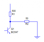
voltage you can get across the collector is worse than 1/10 actually 50/(500+50) = 1/11.
OK, i got that point you are just using potential divider rule but from where this 50ohms come are you taking parallel combination of 100//100, if yes why??
Because it does not matter. I did not draw those circuits to show how to drive a loudspeaker.First, i want to know why 100ohms not 8ohms.
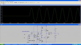
The top circuit is to show how crossover distortion works. It doesn't matter what the resistor is. The distortion is the same with 8ohms or 100ohms or 1000ohms.
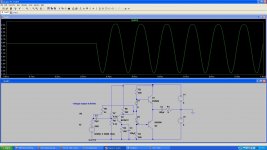
The bottom circuit is to show how to fix crossover distortion, and also to warn about thermal runaway. It is a bad circuit. Thermal runaway can burn your transistors even with no input signal and no load resistor. Again, the load resistance does not matter. Your transistors can burn with a load of 8ohms or 100ohms or 1000ohms or even with no resistor.
Resistors connected to the collectors will not stop thermal runaway.If we will change the resistance emmiter to collector then what will happen, to thermal runaways??
The current through a transistor depends mostly on the base-emitter voltage and the temperature. To double the current, you only need to increase the base-emitter voltage about 20mV. If you increase the voltage another 20 mV, the current will double again.
If you keep the base-emitter voltage the same and increase temperature, the current will also increase. To double the current like this, you only have to increase the temperature by about 10 degrees centigrade. An increase of 30 to 40 degrees will make the current 10 times higher if the base-emitter voltage is kept constant.
Putting resistance between the emitters helps thermal stability. When temperature increases, current will still increase, but not as much because the extra current increases the voltage across the resistance, reducing the base-emitter voltages.
Changing the collector voltage makes very little difference to the current, so connecting resistors in series with the collectors won't help with thermal stability.
Changing the collector voltage makes very little difference to the current, so connecting resistors in series with the collectors won't help with thermal stability.
I know the thermal runaway will not remove but i was clearing my doubt that connecting resistance in series with coll. or emitter will not effect overall working..!!
Hi RR
Please, read what I said again in my earlier posts about re-wiring the circuit. Yes, you have the point that the 100 ohm base resistors are a heavy load for the driver. Yes, again, they are in parallel for the signal. What does this tell you about the impedance of the diodes? Have you seen any references to "small signal impedances" - if not I suggest you look it up in a book.
But the output transistors need a bit of current. The emitter resistor in the driver (R6-400 ohms) limits how far the collector can swing down, so you need to drastically reduce this or eliminate it completely.
800 ohms will not conduct enough current for the output transistors to drive 5V into 8 ohms. Read what I said before, and see if you understand the other points I made.
John

Rr needs to forget about LT spice and instead go and learn how transistors work when placed in a circuit.
Start with emitter follower which is exactly the same as common collector.
Then move on to common emitter and finally common base.
Rr has been given very suitable reading material from well known sites.
He appears to have refused to download any of these tutorials.
Start with emitter follower which is exactly the same as common collector.
Then move on to common emitter and finally common base.
Rr has been given very suitable reading material from well known sites.
He appears to have refused to download any of these tutorials.
That looks like a very good tutorial.
It deals with single ended rather well, although I have only looked at the captions/pics so far.
Find an equally good Push Pull tutorial.
Read them beginning to end. Ask questions on any topic/s you don't understand.
If necessary re-read three or four times.
Only then are you armed and ready to ask a simulator the correct questions.
Hi RR
We're making progress, slowly!
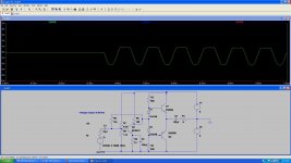
Now you see you cannot drive the output NPN transistor from a 900 ohm resistor. In my earlier post I said you could not use 800 ohms, so 900 is worse.
The point you miss is to stop trying to drive the output stage from the collector of the driver through the centre tap of the bias diodes.
Have you looked up small signal impedances yet? I'm sure there is a web site which explains this.
In your original circuit the 100 ohm bias forced a moderately high current through them and then they have low impedances.
Now you've got 900 ohms the current is low that you switch them off altogether, which causes your clipping. Whatever drive current you like to use now, you cannot push more current into the diodes because they reverse bias and turn off!
PLease note your simulator might say that 2N3906 can drive 5V into 8 ohms. In reality the transistors might blow up. Simulators only tell you what they know about. They don't always know everything they should.
John
We're making progress, slowly!
Now you see you cannot drive the output NPN transistor from a 900 ohm resistor. In my earlier post I said you could not use 800 ohms, so 900 is worse.
The point you miss is to stop trying to drive the output stage from the collector of the driver through the centre tap of the bias diodes.
Have you looked up small signal impedances yet? I'm sure there is a web site which explains this.
In your original circuit the 100 ohm bias forced a moderately high current through them and then they have low impedances.
Now you've got 900 ohms the current is low that you switch them off altogether, which causes your clipping. Whatever drive current you like to use now, you cannot push more current into the diodes because they reverse bias and turn off!
PLease note your simulator might say that 2N3906 can drive 5V into 8 ohms. In reality the transistors might blow up. Simulators only tell you what they know about. They don't always know everything they should.
John
Have you looked up small signal impedance yet? I'm sure there is a web site which explains this.
I don't find any goood tutorial of it..!!
Hi again,
I am not getting clearly then what should be the value of resistance as you were using potential divider to show what is the level of supply voltage ( 1/10 voltage one) across common collector transistor resistance ??
Now you see you cannot drive the output NPN transistor from a 900 ohm resistor. In my earlier post I said you could not use 800 ohms, so 900 is worse.
The point you miss is to stop trying to drive the output stage from the collector of the driver through the center tap of the bias diodes.
I am not getting clearly then what should be the value of resistance as you were using potential divider to show what is the level of supply voltage ( 1/10 voltage one) across common collector transistor resistance ??
Hi RR
Try Wikipedia "diode modelling".
The resistance you need in the upper part of the output stage (npn base) has to be low enough to provide enough base current to drive the emitter current (625 mA).
Start by finding some transistors which will do this. See my earlier posts.
Then calculate the resistor you need for the base current. Make it a bit lower to provide some margin. Divide this into two resistors (see my earlier posts) and add a bootstrap capacitor. You'll see why if you simulate with and without this capacitor.
Throw the collector load resistor on the driver away and connect the collector of the driver to the PNP base. That solves your "backward diode" problem.
You won't need an emitter resistor in the driver as you can use the negative feedback resistors to bias the output voltage rail. You can use a small resistor if you want better DC stability but it will limit the output swing.
Look up how transistors work and see if you can follow putting this circuit together.
John
Try Wikipedia "diode modeling".
I have seen, what the use of it in amplifiers...??
Then calculate the resistor you need for the base current. Make it a bit lower to provide some margin. Divide this into two resistors (see my earlier posts) and add a bootstrap capacitor. You'll see why if you simulate with and without this capacitor.
Yes, i have seen you have divided the Resistance but why..??
Boot strap is used for high input impedance...
- Status
- Not open for further replies.
- Home
- Amplifiers
- Solid State
- How to bias Long tail pair....??