crossover distortion.As you can see in my .62watt amplifiers it is using two Diode as Vbe multipliers for thermal runway...
when i remove these diode the output is distorted, on stimulating i came to know there are working as rectifiers for Q2 base, is this right??
Another item that LT spice cannot teach.
Have you read Self and Leach yet?
Have you added ESP, PASS and Decibel Dungeon to your reading list?
Forget LTsprice until you know what question/s you need to ask it.
Learn what the components and simple circuit do first.
Have you added ESP, PASS and Decibel Dungeon to your reading list?
Forget LTsprice until you know what question/s you need to ask it.
Learn what the components and simple circuit do first.
Hi RR
You also need to add emitter resistors in your 0.62W amp to stabilise the quiescent current. You get thermal runaway if the output transistors get hot and the bias stabiliser does not track the temperature. Since no thermal connection is ever 100% good emitter resistors are needed. If the current increases, the voltage across them increases, and this reduces the current, so helps to make sure that the current is stable with temperature.
For your 0.62W amp I would say you could use 1 ohm resistors.
Normally a transistor is used instead of two diodes because the voltage across it can be adjusted by using a variable resistor in series with a fixed value (to limit the range) between the base and emitter and a fixed resistor between the base and collector. The ratio is nominally 1:1 to give 2x Vbe but in practice will be less than this (Rbc < Rbe). This is known as the "Vbe multiplier".
John
Yes, I tried 2N3055 with MJE2955 in the simulator and they work fine. I prefer plastic transistors though, because they are easier to mount on heatsinks (I think).can we use 2n3055 transistor ??
The first picture below shows the problem. Transistors only start to conduct when the base-emitter voltage reaches about 0.7V so in this circuit there is no output when the input is less than +- 0.7V. Even with a large input, there is bad crossover distortion.As you can see in my .62watt amplifiers it is using two Diode as Vbe multipliers for thermal runway...
when i remove these diode the output is distorted, on stimulating i came to know there are working as rectifiers for Q2 base, is this right??
In the second circuit we fix this by adding the diodes. Diodes also start to conduct at about 0.7V so in this circuit the diodes make sure there is enough voltage between the bases of the transistors to turn them on even when there is no input. Now there is much less distortion in the output.
But there is still a big problem. The transistors may be conducting too much current. Also, when the transistors get hot, their switch-on voltage gets smaller so they conduct even more current, which makes them even hotter. Current and temperature rise until the transistor burns out. This is called "thermal runaway".
To stop that, it is a good idea to put small resistors in series with the emitters, like in circuits I posted before.
Attachments
Thanks for that cool help.!!
OK, if i will connect this below one circuit to amplifiers not at large volume will that increase that volume??
(amplifiers:- is not audio video output one!!)
OK, if i will connect this below one circuit to amplifiers not at large volume will that increase that volume??
(amplifiers:- is not audio video output one!!)
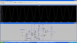
I was just stimulating the above circuit, when i connected the 8ohm speaker directly to sin wave of 2V there was 250mA current
In Common collector the above circuits with diode the current was the same why??
In Common collector the above circuits with diode the current was the same why??
The current through the resistor is the same because the voltage across it is the same. That circuit does not increase voltage; it only has current gain.
The current through the load resistor is the same, but the current drawn from the signal generator is much less.
The current through the load resistor is the same, but the current drawn from the signal generator is much less.
but the current drawn from the signal generator is much less.
How, when i was stimulating i connected the Load resistance of 8ohms directly and the current was almost the same in both schematic ...
and why you are 100ohm Resistance in load , why not 4 or 8ohms??
The current you are telling is exactly right, but how you have collected 10mA??
and if we will the emiiter resistance to collector side will this effect any thing??
and thanks for the nice reply.!!
and if we will the emiiter resistance to collector side will this effect any thing??
and thanks for the nice reply.!!
I have found a LTP with CCS and current mirror works best.
I put a 150r reistor in one leg of the current mirror and a 220r preset in the other leg to adjust DC offset.
I put a 150r reistor in one leg of the current mirror and a 220r preset in the other leg to adjust DC offset.
It is the base current for the transistors plus the current through the resistors....but how you have collected 10mA??
If you bootstrap the resistors with capacitors, it is less.
Yes! There must be resistors at the emitters to avoid thermal runaway.and if we will the emiiter resistance to collector side will this effect any thing??
Attachments
It is the base current for the transistors plus the current through the resistors.
Can you explain more....?
Yes! There must be resistors at the emitters to avoid thermal runaway.
If we will change the resistance emmiter to collector then what will happen, to thermal runaways??

Hi RR
You have forgotten about the 100 ohm loads on the bases of the output transistors. They place a 50 ohm load on the BC547 driver.
To drive an 8 ohm load from +/- 5V you need up to 625 mA peak current. 2N3904,2N3906 don't do this much anyway, so they will need more drive current and maybe go pop!
Start with transistors which have gain at 625 mA, although there are some nice ones like ZTX851 a parallel pair of BC337/BC327 with 1 ohm emitter resistors to share the current will do quite well. Throw away the 500 ohm load, and take the collector of the driver to the cathode of the lower diode (=pnp base), then disconnect and remove the lower 100 ohm resistor, wire it in series with the other 100 ohm resistor and connect a bootstrap capacitor between the junction of these two and the output rail, and you might just get an amp that works.
John
Check the voltage at the base and emitter and collector of Q3. Then maybe you will begin to understand. Also check the current through R5 and R6 and R2 and R3.Please check this circuit i have designed i don't understand why the voltage at 8ohms decrease to mV??
You will learn nothing if you only look at the output.
If you want to understand, you must look at all the voltages and currents in the circuit and think about why they are what they are.
can you explain more, why??You have forgotten about the 100 ohm loads on the bases of the output transistors.
Yes, I tried 2N3055 with MJE2955 in the simulator and they work fine. I prefer plastic transistors though, because they are easier to mount on heatsinks (I think).
The first picture below shows the problem. Transistors only start to conduct when the base-emitter voltage reaches about 0.7V so in this circuit there is no output when the input is less than +- 0.7V. Even with a large input, there is bad crossover distortion.
In the second circuit we fix this by adding the diodes. Diodes also start to conduct at about 0.7V so in this circuit the diodes make sure there is enough voltage between the bases of the transistors to turn them on even when there is no input. Now there is much less distortion in the output.
But there is still a big problem. The transistors may be conducting too much current. Also, when the transistors get hot, their switch-on voltage gets smaller so they conduct even more current, which makes them even hotter. Current and temperature rise until the transistor burns out. This is called "thermal runaway".
To stop that, it is a good idea to put small resistors in series with the emitters, like in circuits I posted before.
First, i want to know why 100ohms not 8ohms.
is there any 100 speaker??
- Status
- Not open for further replies.
- Home
- Amplifiers
- Solid State
- How to bias Long tail pair....??