Nice. That published are the actual working schematics and software?Just gonna add my own tube analyser project to this thread, for the benefit of future generations:
The Valve Wizard
Great projects!
Here's another great DIY tube tracer project that most know about and fits this list.
Röhrenprüfgerät Röhrenmessgerät RoeTest
It's also a great inspiration on how to connect tube sockets to any tester of your own design. Costs add up to +-1000€ in boards + all parts. So while not great money-wise it's still lower than a good VCM163 or L3 or 576 and great to work with (search youtube).
And another DIY curve tracer project/product, the eTracer:
Introduction to the etracer vacuum tube curve tracer project
Introduction to the etracer vacuum tube curve tracer project
Last edited:
One thing I haven't noticed available standard is setting grid 3 to + or - Volts.
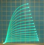
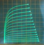
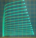
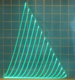
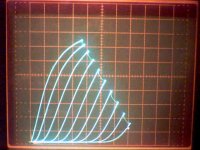
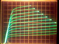
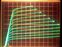
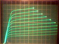
Here is the 4P1L pentode with -15V on grid3, 0V on grid3, +15V on grid3, and last triode mode.
+15V on grid3 looks best for pentode to me. (one could still just use a fixed supply to set grid3 V, if it is not available standard)
Oh yeah, another issue is the ability to scan the plate V from 0 to Vmax and ALSO oppositely from Vmax to 0. Surprisingly these two versions do not always produce the same plate curves, especially around the knees. This is a hysteresis problem that some tubes have. Like 6JK6. You won't likely see the problem either, unless the curve tracer can alternate between the two modes.
Attachments
Last edited:
I would like the software to be available on some other OS the the everAnd another DIY curve tracer project/product, the eTracer:
Introduction to the etracer vacuum tube curve tracer project
changing and never working correct windows.
A statically linked linux binary would run on most platforms.
Last edited:
I went and re-tested the 6JK6 tubes I had here to get a tracer pic of tube hysteresis, and I could not find any that did it anymore.
Apparently this was a gas problem that cleared up via gettering after the 1st time I tested them. So we can forget the tube hysteresis issue (and - to + and + to - scanning thankfully).
N. Crowhurst did once mention a problem of tube hysteresis, but I guess I have not seen it for real yet. Maybe he had some gassy tubes too.
Another one for the record... I've had an eTracer for about a year now:
eTracer Home
This project was inspired by the uTracer, but Chris went off on his own and has been very successful commercially. Works great, well supported.
I barely have time to build amps let alone building the tools to build the amps! So I went with the tested kit route. After you trace a tube another panel gives you a drag-able load line that computes all the predicted power, current and distortion figures for that particular tube. I use that function a lot to come up with the first operating point I want to try out. I (unfortunately) dont know Spice so its all about bread-boarding as fast as I safely can, and impatiently getting to hear some music. I use it to match/test tubes too of course, but I really like the load line tool, saves a ton of time. Chris supports the product on the Facebook side.
I neither use facebook or windows, thus a pass this one!Another one for the record... I've had an eTracer for about a year now:
eTracer Home
This project was inspired by the uTracer, but Chris went off on his own and has been very successful commercially. Works great, well supported.
I barely have time to build amps let alone building the tools to build the amps! So I went with the tested kit route. After you trace a tube another panel gives you a drag-able load line that computes all the predicted power, current and distortion figures for that particular tube. I use that function a lot to come up with the first operating point I want to try out. I (unfortunately) dont know Spice so its all about bread-boarding as fast as I safely can, and impatiently getting to hear some music. I use it to match/test tubes too of course, but I really like the load line tool, saves a ton of time. Chris supports the product on the Facebook side.
Yes! 🙂Nice. That published are the actual working schematics and software?
One thing I haven't noticed available standard is setting grid 3 to + or - Volts.
Here is the 4P1L pentode with -15V on grid3, 0V on grid3, +15V on grid3, and last triode mode.
+15V on grid3 looks best for pentode to me. (one could still just use a fixed supply to set grid3 V, if it is not available standard)
Oh yeah, another issue is the ability to scan the plate V from 0 to Vmax and ALSO oppositely from Vmax to 0. Surprisingly these two versions do not always produce the same plate curves, especially around the knees. This is a hysteresis problem that some tubes have. Like 6JK6. You won't likely see the problem either, unless the curve tracer can alternate between the two modes.
I'm quite astonished to see the first left line from which the bunch of curves appear to emerge getting steeper, i.e. more perpendicular, with increasing g3 voltage. This trick might be useful to increase possible output power with true pentodes. What's the explanation for this? And is this also applicable with beam power tetrodes (if their beam forming plates are brought out on an individual pin, of course)?
Best regards!
These grid 3 knee effects show up primarily in "dual control" tubes like 6LE8, 9KC6 and 6BV11.
(also: 6GX6, 6GY6, 6HZ6, 6AS6, 6BY11, 6DB6, 6DT6, 6AD10, 6888, 7AK7, also: 6BU8, 6KF8, 6MK8, 6GS8, 6HS8 )
They all have a fine pitch grid 3. Some ordinary pentodes will show some effect (assuming g3 is pin available) Most beam tetrodes don't show much effect.
The explanation is that the fine mesh grid 3 at 0V, or neg. V, returns (repels) off axis electrons back to grid 2. (off axis due to perturbing field around grid 1 wires)
Putting some +V on grid 3 can restore normal operation by letting those electrons thru to the plate. There is an optimum +V on g3 that works best, too much +V and g3 starts soaking up electrons itself. Usually around +5V to +15V.
The grid 2 dissipation also goes down dramatically with the +V on grid 3 for these tubes. Allowing the plate diss. rating to be increased some. The 1.7 W 6BV11 with +10V to +14V on g3 becoming somewhat similar to the 3.1 W 6BN11. Grid 1 gm increases dramatically also (just because more electrons make it to the plate ). Rp increases too.
Pete Millett has used the 6BV11 ($1, dual pentode) with +V on grid 3 for a project, I believe.
I don't know why the 4P1L has a fine mesh grid 3, no mention of it on the data sheet, except the Chinese version does mention the +15V. Maybe the original German equivalents had some info. (Bartola: Russian equivalent of the WWII era German Wehrmacht RL2 / 4P6 RF oscillator / transmitting amplifier tube. ) Possibly a fine mesh g3 would lower Miller effect from the plate (increased Rp at least).
See: https://www.diyaudio.com/forums/tubes-valves/160240-suppresor-grid-feedback-6.html#post2083661
..
Attachments
Last edited:
Whoa!!
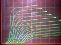
Looking a little further down that Suppressor Grid thread, I found this evidence for tube hysteresis with the 29GK6 tube (6BQ5/EL84). So maybe this ugly thing exists after all. And so - to + with alternating + to - plate V scans are needed to see it. Or was it just a gassy tube?
3rd pic is a 29GK6 with g3 left unconnected!!!
I recall a thread somewhere where someone mentioned that some designer was leaving g3 unconnected for a more "natural" sound. Hmmmm...... I think I replied to that comment with "does he drive around town with his car door unlatched" 😀
Might be interesting to put a high meg. Ohm value pot in series with g3 (to ground or cathode), for some special effects. "train wreck" effects maybe.
https://www.diyaudio.com/forums/tubes-valves/160240-suppresor-grid-feedback-7.html#post2085659
..
Attachments
Last edited:
Typo fix for post #31, line 4
(off axis due to perturbing field around grid 1 wires)
should read:
(off axis due to perturbing field, mainly around +V grid 2 wires)
---------------------------------------------------------------------------------------------
On the tube hysteresis thing, I've seen some data sheets with the alternating plate curves showing the same knee dissimilarity. (but not showing the doubled up knees from re-tracing an odd number of traces seen above) (see non-doubled dissimilar curves below) Probably had their curve tracer set on the max 10 step curves. Takes an odd # of steps, and full wave rectified 240 Hz tracing (4x 60 Hz) to get reversed traces on top of forward traces. (the 2X Step Rate setting on the Tek 576 with 9 steps instead of 10 steps)
Attachments
Last edited:
Can you share layouts (in PDF) of the PCBs you made for the hardware?Yes! 🙂
New CRTs are not available. A Tek 604 display unit with a Tek 577 CRT subbed in are a seamless substitute. There is also a Tek 603 display unit that will take a Tek 577 storage CRT if you want to record curves for tube matching comparisons.
When I was using 5xxx series scopes I found that the X/Y display CRTs could function well. I have one that I used with a 5L4N spectrum analyzer (now in storage).
Me, I use both a uTracer (modded up for the higher voltages) and the 576. Rather than making a series of adapters I just use Pete Millett's bread-boarding accessories.
The 5xxx series scopes do use a big CRT. The problem with the usual scope CRT's is the graticule, 8 X 10 divs, while the 576 and 577 curve tracer CRT's have 10 X 12 divs. The 577 curve tracer CRT (cheaper to obtain used than the 576 CRT) will fit into the 5xxx series, or fits the 604 X-Y display.
The 577 CRT unfortunately does not fit the 576 curve tracer (electrically). I haven't found anything with a compatible CRT for the 576. The Tek 7603 has a big CRT, but is not electrically compatible (mesh magnifier). I do have some Tek 604 X-Y displays, although these seem scarce on Ebay now too. I may put a 577 CRT into one of them.
I have a good condition spare late 576 now, so I probably won't have to resort to these measures. Tek CRTs usually are very long lived besides. The HV inverter xfmr is more likely to cause a problem than the CRT. (re-winding instructions linked below) One just would like some assurance of continuity if purchasing an expensive used curve tracer.
One concern with the 576 is relay K102, used for reversing polarity of the step voltage power supply for + or - stepping. It's a Tek made mini relay, and their V rating for it is just 27V! They use it for 70V as is (20V and 50V, the 576 lets you cross over the 0V grid or gate level by 20V, with the 50V in the selected step range), and increasing the selected step range to 250V for tube stepping is asking for trouble. I make sure to switch off the added boost supply for V stepping tubes before reversing the polarity (NPN / PNP front panel switch, or the INVERT stepping button). I may replace this with a more robust relay at some point, but fortunately tubes are all N type. No -NEED- to be hot switching step polarity. And 300V+ rated relay contacts for DPDT are not abundant.
Another issue is the DUT1/DUT2 toggle switch on the front test plug-in. The SwitchCraft toggle is in NO WAY rated for the 1500V scale. It arced over for me once. I put a new SwitchCraft switch in, and then reduced the 1500V collector sweep down to 750V. Mainly for safety. I still disable the HV (a HV override toggle switch added up front) when changing over DUT1/DUT2 on the 750V scale. (DUT1/DUT2 fast toggling typically used for matching devices)
Here is a link to the Tektronix RPR, which has all the tubes and CRTs used in Tek equipment by Tek p/n. Sites with Tektronix vintage info are getting scarce lately. W140.com is pretty good.
Tek CRT's and tubes:
File:Tek RPR 154- Vacuum Tubes.pdf - TekWiki
HV xfmr winding info for the 576:
http://w140.com/tekwiki/images/4/4e/Tek_120-0612-00.pdf
Last edited:
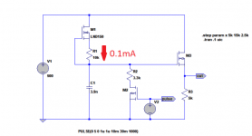
I posted this HV sweep circuit before -- it is adapted from Microchip AN-D12, with the sweeper driving a high voltage MOSFET. The LND150 is a simple 100uA CCs charging a cap (1nF in the apnote, 3.9 in my experiment), and discharged by another Microchip MOSFET.
As i/C = dv/dt everything falls out nicely.
As i/C = dv/dt everything falls out nicely.
Attachments
Firstly, I am wondering if there should be a tube testing sticky thread? There is a lot of useful info over a lot of threads, and I would prefer to monitor all tube testing chatter on a single thread, if possible.
I have a uTracer, and I have been testing tubes, and am discovering just how diverse they can be. I bought a job lot of CV4024 (12AT7WA), and I'd like to sell some with their characteristics traced. Since they are a special quality version of the ECC81, I was expecting the halves would be reasonably closely matched, but that has not proven to be the case. Maybe just one in 10 is within 5%, and so far just 1 has the two curves for 'Vg vs Ia (Va constant)' almost totally aligned.
Just wondering what other peoples' experiences are? What constitutes a matched pair of triodes? < 10% variation at the grid bias point? Conversely, what would be a test fail? Tubes with a very large disparity are still suitable for roles where they have split usage (e.g. driver + PI).
Then I have also been looking at the old used tubes I have. I get the feeling that hardly any tubes ever get thrown away. A tube is swapped into some apparatus, and the old tube gets put back in the new tubes box. One thing leads to another, and it ends up as a tube 'with no guarantee but believed unused' on some auction site. If it is an old power tube with 50% or more dissipation, then it is useful for testing (and should be marked as such), but other cases I'd like to take out of the food chain. What discard criteria do other people have? I'd use the 'typical characteristics' part of the tube data to determine the normal operating points.
The other issue I have had is where the performance is much greater than expected. For instance 170% cathode current, measured internal resistance much less than expected, but 'mu' spot on. What should I be focussing on?
Finally, I want to re-route te power on and HT LED's from the uTracer PCB to the front panel on the case I have. Is it just to swap them with any LED (I have normal sized ones, not miniatures)?
Oh, and one more finally, does anyone have a suggestion for a one-size-fits-all top cap connector?
Billiant idea that I'd second :thumbsup:!Firstly, I am wondering if there should be a tube testing sticky thread?
Best regards!
OldHector, does your Utracer has an external power supply for the tube's heater?
We found that if you use the PS from the PCB Utracer, the results are not accurate, and much lower than what they should be.
I trust your tracer is well calibrated with the 2 10K resistor process etc..
Yes any LEDs would work. I used 3 mm leds on mine.
We found that if you use the PS from the PCB Utracer, the results are not accurate, and much lower than what they should be.
I trust your tracer is well calibrated with the 2 10K resistor process etc..
Yes any LEDs would work. I used 3 mm leds on mine.
- Home
- Amplifiers
- Tubes / Valves
- How-to article presenting a practical tube analyzer