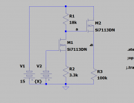
I posted this HV sweep circuit before — it is adapted from Microchip AN-D12, with the sweeper driving a high voltage MOSFET. The LND150 is a simple 100µA CCs charging a cap (1nF in the apnote, 3.9 in my experiment), and discharged by another Microchip MOSFET.
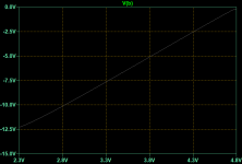
As i/C = dv/dt everything falls out nicely.
Yep. If VTOP is 450 V (out of 500 V), and VBOTTOM is 10 V, then (with 3.9 nF, 3.3 kΩ, 100 µA), repetition period is 17.6 msec, or about 60 Hz, and the discharge pulse needs to be 50 µs.
Just giving numbers to the audience, so to say.
Would be interesting to couple this to a stepped attenuator (electrically active, not mechanical) to derive various grid steps, to produce a complete curve tracer. … I'm thinking of a circuit, but I'm also hopeful that one might use a commonly available DAC or something, from the USB output of one's laptop. At least that route could synchronously control the sawtooth charging capacitor's period with the step-changes in VGRID DAC output.
And of course, once in the USB I/O realm, then it becomes likely to easily digitize (ADC) the 'results', for capture to a file, or a graphical representation, or both.
At the heart … this sawtooth generator and very possibly a well engineered DIY precision power supply. And perhaps Arduino for DAC/ADC business … buffering … stand-alone operation, all that.
⋅-⋅-⋅ Just saying, ⋅-⋅-⋅
⋅-=≡ GoatGuy ✓ ≡=-⋅
… tho I suppose, if the accepted design rule(s) include “a lot of 1960s manual intervention”, then good old fashioned 10-turn 'precision potentiometers' with mated high-accuracy vernier knobs. Once I have a precision power source, simple resistive 10-turn pots do a great job outputting any value between, at 1% precision.
Still, this is the digital age.
I want my computer to collect data, and graph it.
Just about everything about a tube could be collected in less than 60 seconds, even for a pentode with a floating screen grid (not tied necessarily to anode). All that … in turn … can be summarized in 4 high resolution graphs, along the lines of the charts made at the end of the 1960s and early 1970s by RCA for their valves.
Rather beautiful … manual labor … charts.
Even if the only 'digital' part is evaluating valve anode, cathode currents at various calibrated sawtooth voltages and a manual-setting 10× set of knobs for screen, grid bias, settings, even if just that, the same measurements could be made in maybe 2 minutes, with a reasonably well controlled Arduino and Shield.
Nowhere near as complicated an engineering achievement, but attaining just-as-valuable results.
⋅-⋅-⋅ Just saying, ⋅-⋅-⋅
⋅-=≡ GoatGuy ✓ ≡=-⋅
Just stumbled over this thread...
I have an eTracer, and I think it's good. I also don't have Windows, but the software works fine under Linux with Wine. I also don't have (and don't like) Facebook, so I asked Chris if there's another way. In the meantime he added a forum section to his website: Home.
I recently needed a power transistor curve tracer and found two programmable lab-bench power supplies. I wrote some Python code that does what I needed. It should also work for tubes, as long as the powersupplies on your bench will output the required high voltages. It's here: GitHub - mbrennwa/PyPSUcurvetrace: Python program for I-V curve tracing of electronic parts using programmable power supplies Just scroll down to read about it.
I neither use facebook or windows, thus a pass this one!
I have an eTracer, and I think it's good. I also don't have Windows, but the software works fine under Linux with Wine. I also don't have (and don't like) Facebook, so I asked Chris if there's another way. In the meantime he added a forum section to his website: Home.
I recently needed a power transistor curve tracer and found two programmable lab-bench power supplies. I wrote some Python code that does what I needed. It should also work for tubes, as long as the powersupplies on your bench will output the required high voltages. It's here: GitHub - mbrennwa/PyPSUcurvetrace: Python program for I-V curve tracing of electronic parts using programmable power supplies Just scroll down to read about it.
Interesting project! This is a great way to enhance the value of PSUs that support that SCPI connection.
But to start from scratch, the uTracer is such a good deal. For €220 one gets a complete kit with superb instructions. To build two controllable high voltage PSUs for anode and screen, and two more for grid and heater. The integrated solution, with software, is simple to use for characteristic testing, or complex scenarios can be explored with all parameters being changed according the particular dynamic conditions of interest. Fast Fourier transforms are performed to clean up the curves, and data points differentiated for deriving gm and Ri.
It is hard to justify the effort of a home grown solution, unless one needs to test some exotic tubes.
I still have a Sussex under construction, so hope to be able to see how that compares soon.
Have you looked at the Sussex at all? One of the downsides of that solution is the need for a custom transformer, so something like your solution linked to the capabilities of the Sussex, which replicate an AVO mk4, could make for something very interesting!
Last edited:
OldHector, does your Utracer has an external power supply for the tube's heater?
We found that if you use the PS from the PCB Utracer, the results are not accurate, and much lower than what they should be.
I trust your tracer is well calibrated with the 2 10K resistor process etc..
Yes any LEDs would work. I used 3 mm leds on mine.
Thanks for the reply. I have decided that I will make a provision to connect an external heater supply. Do you think it is prudent to make it selectable with a DPDT switch, so the existing supply is isolated?
I did spend a lot of time calibrating, but since then I have switched PC's, so I need to copy across the calibration file from that machine. I recently bought an AVO mk3, and comparing results with that, I did not notice any big discrepancies.
The main issue I have is that unless the tube is spot on, I am not really sure how to interpret the results. In that way the AVO is better since there are a sequence of tests (including short circuits and current leakage due to gas), and ultimately the tube is green, red, or marginal.
Last edited:
With regard to the external heater supply -- MPJA.com has a little Li charger/LED driver which can be used as CCS for up to 3 amps without external cooling -- and you can buy it cheaper on EBay if you look -- but shipping from china probably means a delay. I bought two with my last order (I use MPJA for adapter boards): Little switcher for tube filament supply
Do you think it is prudent to make it selectable with a DPDT switch, so the existing supply is isolated?
On mine I just run wires from the external heater supply into the heater patch sockets on the uTracer.
- Home
- Amplifiers
- Tubes / Valves
- How-to article presenting a practical tube analyzer