Here’s a new article from Tronola.com covering construction and performance tests of a tube analyzer and curve tracer which is feasible for many hobbyists. We added a custom-designed, precision heater supply to enhance the accuracy of the well-known uTracer kit and then compared the performance with our previously published Vacuum Tube Analyzer design. The results are pretty impressive. You can read all about it here:
Tube Analyzer You Can Build page1
Enjoy! Steve Lafferty
Tube Analyzer You Can Build page1
Enjoy! Steve Lafferty
Last edited:
Just gonna add my own tube analyser project to this thread, for the benefit of future generations:
The Valve Wizard
The Valve Wizard
This is inspiring ! Will there be boards/kits in the shop ?Just gonna add my own tube analyser project to this thread, for the benefit of future generations:
The Valve Wizard
I have built myself 2 uTracers, but i diverted from the main line by using a
separate box containging one socket and a D-25 connector. This way i can
have short wires and no plugboard as i used D25 connectors wired for each
type of tube.
The boxes with sockets and plugs may be reused in an analogue circuit for
testing noise and microphonics, using the same personality plugs.
Here’s a new article from Tronola.com covering construction and performance tests of a tube analyzer and curve tracer which is feasible for many hobbyists. We added a custom-designed, precision heater supply to enhance the accuracy of the well-known uTracer kit and then compared the performance with our previously published Vacuum Tube Analyzer design. The results are pretty impressive. You can read all about it here:
Tube Analyzer You Can Build page1
Enjoy! Steve Lafferty
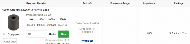
What are those beads which are connected to the tube socket pins ? Never saw those before.
Look like large ferrite beads, to supress RF oscillation. Needs to be close to the socket, you can't just place them after the patchbay, so all the tube pins need them as pinouts vary.
Look like large ferrite beads, to supress RF oscillation. Needs to be close to the socket, you can't just place them after the patchbay, so all the tube pins need them as pinouts vary.
Ah, I already presumed this but never saw that special type.
Any idea where I can purchase these?
Wiring the bases in a tube tester
Hi Joe, I've just recently built one of these. I bought my beads from RapidOnline ... (can't use the link for some reason).
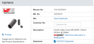
Ron from uTracer recommends the Wuerth ones ...
ferrite bead
Being a cheap skate, I bought the ones from Rapid. There are different approaches to including them in the wiring, though both are linked to the AVO solution. The key is to have a loop from the selector to the bases and back to the selector, and I think keeping similar loop lengths is also important. The difference is whether to add the beads at the pins (which I am aiming to do with smaller beads), or have them as part of the loops for each pin, but not on each base (as in the diagram linked to in the previous post).
I have my top plate built now, with 2mm plugs and 5 bases (B9A, B7G, B8A, Octal, Loctal), and I have put off the soldering session until I have a few hours free.
There is also another home brew tester on Vintage Radio called 'The Sussex'. That is a cheaper solution, and more faithful to the AVO concepts. The board was less than £10, so I have one of those that I am building too as another project.
The Sussex VT1
HTH Richard
Hi Joe, I've just recently built one of these. I bought my beads from RapidOnline ... (can't use the link for some reason).
Ron from uTracer recommends the Wuerth ones ...
ferrite bead
Being a cheap skate, I bought the ones from Rapid. There are different approaches to including them in the wiring, though both are linked to the AVO solution. The key is to have a loop from the selector to the bases and back to the selector, and I think keeping similar loop lengths is also important. The difference is whether to add the beads at the pins (which I am aiming to do with smaller beads), or have them as part of the loops for each pin, but not on each base (as in the diagram linked to in the previous post).
I have my top plate built now, with 2mm plugs and 5 bases (B9A, B7G, B8A, Octal, Loctal), and I have put off the soldering session until I have a few hours free.
There is also another home brew tester on Vintage Radio called 'The Sussex'. That is a cheaper solution, and more faithful to the AVO concepts. The board was less than £10, so I have one of those that I am building too as another project.
The Sussex VT1
HTH Richard
Attachments
Possibly, if I get enquiries.This is inspiring ! Will there be boards/kits in the shop ?

Just gonna add my own tube analyser project to this thread
I would add mine, but it is in early development, and in a constantly evolving state, and at this moment it is non functional (new power supply design). If it ever gets to a reproducible state, I'll publish it here somewhere.
A few years ago I was given a Hagerman Vacutrace which I used to explore some new and unique vacuum tube technology. Unfortunately there were several limitations associated with the Vacutrace. The biggest limitations were the lack of ability to step the control grid positive or step the screen and suppressor grids at all. The Plate voltage will go to 390V on mine, but the grid voltage only goes negative, and stops at -67 volts. It also only works well with a true analog scope, or at least didn't play well with my Rigol.
I also want the capability to multi-step multiple elements of the tube both negative and positive to generate families of non traditional curves. B+ voltage above 390 V (Hagerman limit) with current pulses to 500 mA or more. The ability to do short pulse curve tracing, possible continuous or long (variable) pulse curve tracing, and continuous Gm measurements at fixed voltage and current to weed out drifting tubes (fairly common in TV sweep tubes).
At first, I attempted to circumvent the shortcomings of the Vacutrace with external circuitry. As the circuit discovery aspect grew more and more non traditional (different drive signals applied to two different grids simultaneously), the Vacutrace and breadboard full of opamps and Chinese power supply boards could not do what I needed.
This external circuitry grew far too complex, so I added a Teensy 3.6 small form factor Arduino compatible board. It's on board "16 bit" A/D converters are used for measurements (real world accuracy is about 12 to 13 bits) which is far better than the Vacutrace and good enough when tube and part variations are FAR WORSE.
The original concept used a DIY mosfet / resistor ladder operating from the digital output pins to step the output voltages on one of those 0-390 volt boost converters you find on Ebay or Amazon. They don't like being wired in series, working backwards from the +36 volt heater supply to make -150 to +36 volts, or pumping out 200 mA continuously. That was unreliable, so I am constructing a "real" bipolar power supply with an Antek toroid.
A 36 volt SMPS supplies the heater voltage directly for big TV sweep tubes. An Amazon sourced variable buck converter steps that down to lower voltages as needed, but exhibits some drift when trying to run 2A3's (2.5 V @ 2.5A). I still have a few 42 volt tubes that haven't been tested and some small 50 volt tubes. It has been reliable at 6.3, 12.6, 25, 26 and 36 volts, but I will revisit it at a later date.
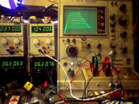
For now I am using the terminal window in the Arduino software to grab the data and plot it in Excel. An RPi with a color 7 inch LCD will do this task if I can figure out how to do it.
As with others I have borrowed ideas from the Vacutrace, the VTA, and other random ideas found on the web. The VTA is the ultimate piece of HP / Tek like equipment. It is complete overkill for my needs (0.1% accuracy), but the Vacutrace is in the 2 to 5% range for measurements and I'm using an old Tek 2335 scope with a 4 inch screen for curve display. In some cases I have just turned the knobs, read the meter, and plotted the results in Excel in order to post them here. I think there is plenty of room in between those extremes for a simple box with advanced capabilities.
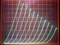
Note that my DIY device generated the data for these curves. There is still some error with the grid voltage step sizes (old resistor ladder approach). This is actually a 6GF5 TV sweep tube with drive applied to multiple elements. Note that the "triode" curves go to 550 volts, well beyond the screen grid ratings. Short pulses allow me to hit 40 watts on a 9 watt tube. Attempting get pulsed curves like these from a 40 watt 36LW6 resulted in dead parts in the DIY tracer.
Attachments

Last edited:
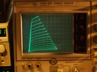
Its not too hard to convert a Tektronix 576 curve tracer for doing very capable tube duty. The step amplifier gets four transistors upgraded (350V) for higher voltage and the step feedback circuit gets a pot added to set higher gain. (a knob on the side to adjust continuously, a step V calibration selector also provided already) The original 10 steps of +/- 2V max are now converted to 15 steps of up to +/-15V (250V step range, with 250 mA current capability for driving grid 2 if needed). The step voltage power supply gets upgraded with an industrial 120V:230V xfmr internally. Step V supply boost and the increased step gain can both be switched out easily if you want to do original SS curve tracing.
The DUT1/DUT2 interface gets a mod to supply screen V when a tube is selected. (external screen supplies, one for each tube, Xantrex XT-250 0.25 with digital readouts and current limiting )
External Xantrex HPD 60-5 supplies provide tube heater power (up to 60V and 5 Amp)
An external 60V supply provides for an optional minimum plate V, if you want to avoid the high screen current region in plate knees.
As designed, it will do plate traces up to 1500 V and 220 Watts, high current on lower V ranges. I modded the 1500V range down to 750 V for safety (provision provided). Not hard to do. I usually use the 350 V range (more like 425V with high line voltage). And the minimum plate V option increases the plate sweep by another 60 V as well.
It also provides for external signals for either the X or Y display parameter. This can be useful if you want to show screen current for example. (use Tek AM503 DC current probe)
The main problem is finding a good Tek 576 for a reasonable price. I have recently acquired a spare one for $575 that is in good condition. (University sourced, almost like new) Typicall Ebay offers are up in the $1500 or more range for one that can display curves. But occasionally I see ones in the $400+ range, usually without a display. Watch out for ones that have had extreme use (production probably), the knobs are cracking and the switches feel flaky, there is a surface shine around the Collector V Variac knob. Push-buttons can be flaky, especially the "Invert" Display button for PNP devices. Excellent service manuals are available on Ebay. Definitely quality built stuff, but pretty darn old now. New CRTs are not available. A Tek 604 display unit with a Tek 577 CRT subbed in are a seamless substitute. There is also a Tek 603 display unit that will take a Tek 577 storage CRT if you want to record curves for tube matching comparisons. Although the standard DUT 1 and DUT 2 switching works quite well for matching tubes without storage capability.
The only spare parts available are from another, usually worn out, 576. They weigh 75 lbs, so shipping is expensive and the shippers like to drop them off a truck. Make sure the seller packs it extremely well, foamed in place. Used Tektronix knobs are expensive. The HV supply for the CRT is probably the big show stopper if it is gone. Tek has supplied winding instructions for the ferrite xfmr online, around 1000 turns of fine wire.
A digital camera works fine for taking curve pics to put online.
Attachments
Last edited:
For us more casual DIYers, bang for buck is important.
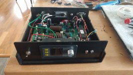
My uTracer was €220, delivered anywhere in world, with all parts, plus extensive instructions on building and sequential testing. It was a bit daunting in assembly, since it is a high density board, with chip sockets, and the biggest delay was getting hold of some leaded solder, which had to come from the States (all channels closed here in Sweden). My existing solder was 1.2mm, and I wanted Hester 0.6mm. I didn't fancy having to use a higher melting point solder with all those semiconductors.
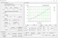
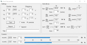
I was able to link up a valve base via a connector strip (for mapping pins) and I was curve tracing the halves of 12AT7's, in a single test, with no extra expense required. The supporting software is excellent, and tests can be run in many permutations.
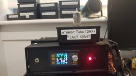
Pictures with testing an EL84 sourced from an old radio ...
I also bought an AVO MK3, since once came up locally for a reasonable price, but now I am wondering if I should keep it.
My uTracer was €220, delivered anywhere in world, with all parts, plus extensive instructions on building and sequential testing. It was a bit daunting in assembly, since it is a high density board, with chip sockets, and the biggest delay was getting hold of some leaded solder, which had to come from the States (all channels closed here in Sweden). My existing solder was 1.2mm, and I wanted Hester 0.6mm. I didn't fancy having to use a higher melting point solder with all those semiconductors.
I was able to link up a valve base via a connector strip (for mapping pins) and I was curve tracing the halves of 12AT7's, in a single test, with no extra expense required. The supporting software is excellent, and tests can be run in many permutations.
Pictures with testing an EL84 sourced from an old radio ...
I also bought an AVO MK3, since once came up locally for a reasonable price, but now I am wondering if I should keep it.
Attachments

Last edited:
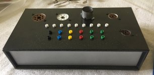
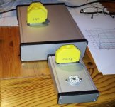
Here is mine. I've use separate tube enclosure per family, for simplicity.
I pick the right enclosure, load the Utracer setup and measure.
Simple and error free. I ended up with 10 enclosures covering all the tubes I use.
I pick the right enclosure, load the Utracer setup and measure.
Simple and error free. I ended up with 10 enclosures covering all the tubes I use.
Attachments
Replying to JoeAlders question in posts #4, #6:
(Sorry for the delayed reply; there was a problem with my notifications which I just found and fixed.)
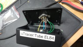
--- (I thank those who have already provided assistance.) Those sleeve-beads are: Fair-Rite #43 material sleeve bead, 120ohm, ID=.090" OD=.200 L=.437. Mine came from Mouser Electronics, their Part# 2643005701, current price $0.10 each.
These beads fit the hookup wire specified in the Bill of Materials (BOM): #18, 600V, polyolefin, irradiated. The #18 wire was used to support the high available heater current (3-5A) from the add-on heater supply included in the project. This affordable wire has fairly small overall diameter while still supporting the high voltage and current. The irradiated insulation is impervious to brief encounters with a soldering iron, does not shrink-back from soldering and is easy to strip.
Full documentation (including the BOM) can be found near the bottom of page 2 of the article. Tube Analyzer You Can Build page2
By the way, the "µTracer/HR System Schematic (GIF)" has a brief description of the bead strategy, which is my interpretation of the loops recommended by Ronald Dekker. However, one feature of this project is that the add-on heater supply supports remote sensing of the actual voltage at the socket pins and this requires two separate lines going to each pin (one for driving and one for sensing). This increases the number of beads needed but greatly increases the accuracy of the heater voltage seen by the tube.
I'm always happy to answer any questions about the article.
(Sorry for the delayed reply; there was a problem with my notifications which I just found and fixed.)
What are those beads which are connected to the tube socket pins ? Never saw those before.
--- (I thank those who have already provided assistance.) Those sleeve-beads are: Fair-Rite #43 material sleeve bead, 120ohm, ID=.090" OD=.200 L=.437. Mine came from Mouser Electronics, their Part# 2643005701, current price $0.10 each.
These beads fit the hookup wire specified in the Bill of Materials (BOM): #18, 600V, polyolefin, irradiated. The #18 wire was used to support the high available heater current (3-5A) from the add-on heater supply included in the project. This affordable wire has fairly small overall diameter while still supporting the high voltage and current. The irradiated insulation is impervious to brief encounters with a soldering iron, does not shrink-back from soldering and is easy to strip.
Full documentation (including the BOM) can be found near the bottom of page 2 of the article. Tube Analyzer You Can Build page2
By the way, the "µTracer/HR System Schematic (GIF)" has a brief description of the bead strategy, which is my interpretation of the loops recommended by Ronald Dekker. However, one feature of this project is that the add-on heater supply supports remote sensing of the actual voltage at the socket pins and this requires two separate lines going to each pin (one for driving and one for sensing). This increases the number of beads needed but greatly increases the accuracy of the heater voltage seen by the tube.
I'm always happy to answer any questions about the article.
Strongly agree with Stephen on an external PS which greatly improves the accuracy of the measurement, and using beads, as I stumble on this when testing my tracer.
I made my uTracer with one box for each socket + a d-sub connector as ident fo reach tube:
uTracer pictures.
uTracer pictures.
Attachments
Last edited:
Neat!
You just need a camera, some OCR software and a robotic arm, and you will have solved the problem with 'the krank in front of the keyboard' ;-)
What did you do with ferrite beads in your setup?
You just need a camera, some OCR software and a robotic arm, and you will have solved the problem with 'the krank in front of the keyboard' ;-)
What did you do with ferrite beads in your setup?
Nothing, they are not needed. Short leads and direct connections.Neat!
You just need a camera, some OCR software and a robotic arm, and you will have solved the problem with 'the krank in front of the keyboard' ;-)
What did you do with ferrite beads in your setup?
The few grid-stoppers that is needed is placed in the D-sub connector.
I love this idea!I made my uTracer with one box for each socket + a d-sub connector as ident fo reach tube
Replying to JoeAlders question in posts #4, #6:
(Sorry for the delayed reply; there was a problem with my notifications which I just found and fixed.)
--- (I thank those who have already provided assistance.) Those sleeve-beads are: Fair-Rite #43 material sleeve bead, 120ohm, ID=.090" OD=.200 L=.437. Mine came from Mouser Electronics, their Part# 2643005701, current price $0.10 each.
These beads fit the hookup wire specified in the Bill of Materials (BOM): #18, 600V, polyolefin, irradiated. The #18 wire was used to support the high available heater current (3-5A) from the add-on heater supply included in the project. This affordable wire has fairly small overall diameter while still supporting the high voltage and current. The irradiated insulation is impervious to brief encounters with a soldering iron, does not shrink-back from soldering and is easy to strip.
Full documentation (including the BOM) can be found near the bottom of page 2 of the article. Tube Analyzer You Can Build page2
By the way, the "µTracer/HR System Schematic (GIF)" has a brief description of the bead strategy, which is my interpretation of the loops recommended by Ronald Dekker. However, one feature of this project is that the add-on heater supply supports remote sensing of the actual voltage at the socket pins and this requires two separate lines going to each pin (one for driving and one for sensing). This increases the number of beads needed but greatly increases the accuracy of the heater voltage seen by the tube.
I'm always happy to answer any questions about the article.
Thank you very much slafferty for this explanation!
And I really like this "power and sense" approach for measuring the heater voltage.
- Home
- Amplifiers
- Tubes / Valves
- How-to article presenting a practical tube analyzer