If you think so ....
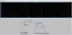
0.5A pulses trough diodes, 270mA charging pulses on last C, 600mVpp sawtooth "hum".
It's only the lagre capacitance charging device, not PSU.
Very interesting. One of these days, I'll figure out spice. Thanks for modeling it. That's actually one of the RC filters in my power amp PSU. I'm actually surprised there's that much ripple but I have extra stages of filtering in mine and it's push pull so we have a good CMRR from the OPT. I should measure the ripple I actually have from ground to plate.
imho...ripple voltage is first consideration....
ripple voltage is directly proportional to load current, and inversely proportional to C...
ripple voltage is directly proportional to load current, and inversely proportional to C...
No, it wouldn't sound different with speakers that went down to 20hz.When I added a 33 uF cap to the 1.5 uF on the 30 tube power supply node, it didn’t make any audible difference to the sound. However, the speakers I use are La Scalas, and have a -3 DB point at around 57 Hz. I would imagine that the change would have been more obvious if my speakers went down to 20 Hz.
That's because - as I kept saying in the other thread - the PS forms a low pass filter, not a high pass filter.
A 10k R followed by a 1.5uf cap forms a low pass filter with a cutoff frequency of 10.6 Hz. If you have a 10k R followed by a capacitance of 34.5uf, the cutoff frequency drops to 0.46 Hz.
As I understand it, in theory, this would only affect PS ripple except that the earlier stages have filtered it out already.
Yes, I think those are the key factors.The graphs really illustrate the impact of capacitor value changes on the recovery time/time constant and on the degree to which the cap is depleted on transients.
Please correct me if I’m wrong, but wouldn’t the sort of jump in current draw used in your sim never actually happen with a single ended amp?
Although Loesch's article deals only with the B+ cap that supplies the output tubes, his approach is to calculate the size of the cap based on the most extreme musical demands he can think of. But, if you don't listen to such music, a more moderate approach should work fine.It's shows the PSU behaviour at worst case. . . . But some electronic "music" may contains extreme sound effects, and -for example- footdrum punch also can cause surprises for SE amps.
This is why I see it as a bit of a balancing act. Use a cap that's large enough to deal with music that's relatively demanding yet small enough so that the recovery time isn't too slow.
But as you pointed out, you were unable to hear any difference even though the effects are measurable. So, while this is an interesting technical / theoretical discussion, is it really that important to try to be so exact when choosing a cap value for the input tube supply?
FlaCharlie: I've read over the Loesch article a few times. He may be wrong to do so, but he does work out a high pass in his equations.
First, he picks a capacitor size based upon the plate resistance of the tube in question and the frequency response of the high pass created by the node's capacitor and 1/10th of the plate resistance of the power tube. At this point, he also mentions that for a regular linear supply, the resistance of the entire supply, up to the power tube's node, should be less than 10% of the power tube's plate resistance. This is the quote...
"The Impedance of the Powersupply must be small in comparison to the Anode (Plate) Impedance of the
Valve the PSU feeds at all frequencies at which the Amplifier is being operated. The load-impedance does
not factor at all here. I suggest a ABSOLUTE MINIMUM RATIO of 1:10 between Anode Impedance and
PSU Impedance for the whole Frequency Range required for the Amplifier. For a 300B the Anode
Impedance is around 700 Ohm. For a lowest Frequency of 4Hz (my definition of audibility of Audio
Frequencies is 4Hz-100kHz @ -3db or 20Hz - 20kHz @ -0.1db) our PSU-Impedance should be hence less
or equal to 70 Ohm (700 Ohm / 10). The rest is simple math. It leaves us with the result that the final filter
capacitor for a conventional PSU arrangement, should be at least 560uF when used with a single 300B."
He then works out a time constant based, as you mention, on very strict criteria of 40 MS. Using 40 MS and the capacitance of 560 uF, he works out what the entire resistance of the entire power supply should be under...
"So with our original 300B PSU above we are looking at a solution like this:
For ideal conditions we have about 560uF as final Filter/Reservoir Capacitor. This is an Elna Cerafine
Capacitor (or Film or whatever you like and what keeps distortion low).
40mS / 560uF = DCR in kOhm = 0.071kOhm
This suggests as DCR of no more than 71 Ohm for the entire PSU :
(((Transformer Primary DCR x square of the stepup Ratio) + Transformer Core loss [estimated at 5%] +
Transformer secondary DCR ) Multiplied by 1.4 [for Capacitor Input only]) + Rectifier Impedance + DCR
of all Chokes
Now this a tall order."
From what I gather from posts on this thread, the assumptions that Loesch bases his calculations on are questionably strict, but I don't think anyone disagrees with the methods used in a general sense. However, I am no expert and may be misunderstanding. I had to work through the equations, several times with different examples in order to get a sense for them.
"The load-impedance does not factor at all here. "
Hmmm... it's only true, if the 300B is working in "tube tester".
If it's a real amplifier, the reflected load act as anode load impedance, so it's part of examined equipment.
BTW, why don't you let go of this 1:10 ********?
The "suggested" resistance is unenforceable, the "suggested" last capacitor value is pointlessly large, moreover, it is not taken into account the other parts of PSU (mainly the rectifier and PT).
Most of the real 300B PSUs (99.9...%) not like this.
Attachments
"The load-impedance does not factor at all here. "
Hmmm... it's only true, if the 300B is working in "tube tester".
If it's a real amplifier, the reflected load act as anode load impedance, so it's part of examined equipment.
BTW, why don't you let go of this 1:10 ********?
The "suggested" resistance is unenforceable, the "suggested" last capacitor value is pointlessly large, moreover, it is not taken into account the other parts of PSU (mainly the rectifier and PT).
Most of the real 300B PSUs (99.9...%) not like this.
euro21: The suggested impedance is enforceable if you use the tube regulated supply that Loesch presents at the end of the article. However, his criteria and assumptions are "ideal" and probably not really necessary for many applications.
I believe that he includes the PT and rectifier in the total impedance...
"In order to really kill noise, we need two Filter-Cells (read C-L-C-L-C), combined with suitable further
noise Filtering. We need Chokes with likely less 20 Ohm DCR (together accounting for 40 Ohm of the 70
Ohm) and than have only a further 30 Ohm for the Rectifier and Mains-Transformer. I'm not sure if this is
doable at all with valve-Rectification. Even with Solid State Rectifiers it will be tricky."
In my soon to come 300B amp build, I am going to use his regulated supply, which is tuned for 15 Ohms of impedance...
"I have implemented a very similar regulator circuit myself. In order to optimise the subjective sonics I
ended up tuning the circuits open loop gain and open loop frequency response for best transient response
with the applied output capacitors (47uF Ansar X 2). The regulator was also quite deliberately optimised for
a internal impedance that is much higher than possible with this circuit (JC Verdier shows << 1 Ohm).
In fact, with the PSU impedance tuned to 15 Ohm and 94 uF output capacitance we get a time constant of
1410uS equivalent to a take-over frequency of 112Hz. Below this the regulated supply determines sonics,
above this the high quality supply capacitors progressively become dominant, above 440Hz they are
practically solely responsible. I found the sonic difference of the Circuit as shown here compared to the
original publication quite startling, though as discussed above the reasons for this behaviour are simple and
straightforward physics and not voodoo."
In a general sense, do you agree that it is better to keep power supply impedance at a minimum?
Thanks for your persistence here, this is very interesting to me as well.
Jacob Greenfield: If you are referring to my persistence, you are
most welcome. That said, it is getting tedious even to me as the instigator...
FlaCharlie: I've read over the Loesch article a few times. He may be wrong to do so, but he does work out a high pass in his equations.
It is getting tedious and I apologize if I'm the one who is making it so . . .That said, it is getting tedious even to me as the instigator...
But, here's the high pass filter calculator I posted in the other thread.
High Pass Filter Calculator
It shows the configuration of a high pass filter, which is a cap followed by a resistor to ground. This is what you see in cap coupled stages. The coupling cap followed by the grid leak resistor.
I keep bringing this up because I don't see the same configuration of parts in the PS. When I look at a PS, I see a resistor followed by a cap to ground. Same parts (resistor and cap) but a different configuration. A resistor followed by a cap to ground forms a low pass filter.
Am I blind? Or perhaps I'm overlooking some subtlety? Please show me where the high pass configuration occurs in the PS.
Also, in the other thread, I performed a simple test in the PS node that supplies my input tube. I fed a steady 50hz signal into the amp. The section of my PS that feeds the input tube consists of a 3.9k resistor followed by a cap to ground. I tried 3 different values for the cap: 50uf, 5uf and 0.1uf.
According to the high pass calculator, a 3.9k R and a 50uf creates a high pass with a rolloff frequency of 0.82 Hz. A 3.9k R and a 5uf creates a high pass with a rolloff frequency of 8.2 Hz. And a 3.9k R and a 0.1uf creates a high pass with a rolloff frequency of 408.3 Hz.
Thinking that a rolloff of 408 Hz might not be extreme enough, I just now tried a 0.01uf cap. With this value the rolloff frequency should be 4.08 kHz if a high pass filter is being formed.
So, if a high pass filter is created, the 50hz signal should have been attenuated significantly when the 0.1uf cap was in place and essentially inaudible with the 0.01uf.
I could not hear any difference in volume regardless of which cap was used.
Am I missing something here? It's possible. If so, could someone please explain why the volume level of the 50 Hz tone was unaffected if the PS forms a high pass filter.
Or, does the configuration of a power supply NOT form a high pass filter?
Last edited:
It is getting tedious and I apologize if I'm the one who is making it so . . .
But, here's the high pass filter calculator I posted in the other thread.
High Pass Filter Calculator
It shows the configuration of a high pass filter, which is a cap followed by a resistor to ground. This is what you see in cap coupled stages. The coupling cap followed by the grid leak resistor.
I keep bringing this up because I don't see the same configuration of parts in the PS. When I look at a PS, I see a resistor followed by a cap to ground. Same parts (resistor and cap) but a different configuration. A resistor followed by a cap to ground forms a low pass filter.
Am I blind? Or perhaps I'm overlooking some subtlety? Please show me where the high pass configuration occurs in the PS.
Also, in the other thread, I performed a simple test in the PS node that supplies my input tube. I fed a steady 50hz signal into the amp. The section of my PS that feeds the input tube consists of a 3.9k resistor followed by a cap to ground. I tried 3 different values for the cap: 50uf, 5uf and 0.1uf.
According to the high pass calculator, a 3.9k R and a 50uf creates a high pass with a rolloff frequency of 0.82 Hz. A 3.9k R and a 5uf creates a high pass with a rolloff frequency of 8.2 Hz. And a 3.9k R and a 0.1uf creates a high pass with a rolloff frequency of 408.3 Hz.
Thinking that a rolloff of 408 Hz might not be extreme enough, I just now tried a 0.01uf cap. With this value the rolloff frequency should be 4.08 kHz if a high pass filter is being formed.
So, if a high pass filter is created, the 50hz signal should have been attenuated significantly when the 0.1uf cap was in place and essentially inaudible with the 0.01uf.
I could not hear any difference in volume regardless of which cap was used.
Am I missing something here? It's possible. If so, could someone please explain why the volume level of the 50 Hz tone was unaffected if the PS forms a high pass filter.
Or, does the configuration of a power supply NOT form a high pass filter?
FlaCharlie. I couldn’t hear any difference in the 30/6P15P-EV amp either when I changed the capacitor value from 2.2 uF to 35.2 uF. When I increased the capacitance on my 6N1P-EV/KT120 amp, it muddied the sound. Hardly scientific, I know. To be honest, at this point, I still don’t fully understand what is going on. That may be because my pencil isn’t very sharp, but I’m just a hobbyist trying to learn. Some folks feel angry when confronted with a hobbyist trying to learn. Especially when the hobbyist doesn’t learn fast enough. Perhaps the right answer has already been presented and I didn’t understand it, but I do think I understood what Loesch’s article had to say.
I would love to have an answer to your questions as well...
If so, could someone please explain why the volume level of the 50 Hz tone was unaffected if the PS
forms a high pass filter. Or, does the configuration of a power supply NOT form a high pass filter?
A power supply, which by definition produces DC (that is, 0 Hz) voltage, is a low pass filter.
Last edited:
I believe that he includes the PT and rectifier in the total impedance...
I would be surprised.
The usual tube rectifier requires 50-100R DCR PT secondary, and has significant impedance.
Even the "brutal" tube rectifiers (for example mercury vapour) has few- few ten Ohm impedance.... and requires low DCR secondary (aka. brutal current capability without sag).
I'm not a fan of SS rectifiaction in SE amps, and it requires different smoothing technology than tube rectification.
Almost impossible make large (for example 10H) inductance with few Ohm DCR ... except toroid ones ... or it's rather 10kg weight, than 1-2kg.
You would use small output impedance stabilized PSU (mainly shunt stab. type), but IMHO it's a vaste of money, part and dissipation.
Acceptable sollution using Tom's Maida II stabilizer or similar ... but in my case it always gets out of SE amp.
I'm not a fan of vacuum rectification - it's the one thing SS parts do better every time. I also don't see why it requires different smoothing to use HER308 vs 5U4GB. Except for max capacitance input filter of course.
My only SE amp uses FW rectification into a simple CRC filter. 36mF - 1R - 36mF. It's a MOSFET output though. I get a few mV of ripple on the PSU that outputs 75V@4A.
My only SE amp uses FW rectification into a simple CRC filter. 36mF - 1R - 36mF. It's a MOSFET output though. I get a few mV of ripple on the PSU that outputs 75V@4A.
IMO, the last true advantage of vacuum rectifiers lies in the "soft" start of types constructed with cathode sleeves. Directly heated vacuum rectifiers conduct nearly as quickly as SS.
I can see vacuum rectification for a preamp project, particularly if the bottle(s) are already on the parts pile. I reject the notion of vacuum rectification in a new power amp project, as the "soft" start issue is addressable.
I can see vacuum rectification for a preamp project, particularly if the bottle(s) are already on the parts pile. I reject the notion of vacuum rectification in a new power amp project, as the "soft" start issue is addressable.
If adding capacitance muddied the sound, I suspect the added cap was an electrolytic. To determine if it was actually the extra capacitance that was the culprit, you'd need to use a film cap.FlaCharlie. I couldn’t hear any difference in the 30/6P15P-EV amp either when I changed the capacitor value from 2.2 uF to 35.2 uF. When I increased the capacitance on my 6N1P-EV/KT120 amp, it muddied the sound. Hardly scientific, I know.
I figure it's best not to put too much stock in comparisons when two different amps are used in the test. If the results are different, it may simply be because the circuits are different and that different circuits react in different ways.
I am also just a hobbyist and my brain doesn't deal with the theory and math very well at all. My approach is based on a very basic and limited understanding and I just try to proceed in a logical way.To be honest, at this point, I still don’t fully understand what is going on. That may be because my pencil isn’t very sharp, but I’m just a hobbyist trying to learn. Some folks feel angry when confronted with a hobbyist trying to learn. Especially when the hobbyist doesn’t learn fast enough. Perhaps the right answer has already been presented and I didn’t understand it, but I do think I understood what Loesch’s article had to say.
I would love to have an answer to your questions as well...
Re: Loesch's article . . . the details are over my head but I get the sense that he may be omitting some (possibly important) factors in order to make his theory more plausible. Some of the more technically gifted posters seem to be trying to point that out. At least that's my interpretation.
Another aspect that I suspect is muddying the waters is that Loesch is writing about the B+ supply for the output tubes and your inquiry is about the cap that supplies the input tubes. So, even if Loesch's ideas make sense for the output tube supply, that doesn't mean that they apply to the input tube supply. It may well be an "apples vs oranges" comparison. Or perhaps "oranges vs lemons".
I figure it's best to forget about Loesch's theories and focus on the discharge / recharge issue. But, as I recall, even the data on that aspect that was presented earlier focusses on the output tube cap. Similar measurements of the input tube's supply cap are needed in order to reach a more informed conclusion.
Which brings me back around to:
I ordered some 15uf DC Link caps and that's probably what I'll use. A compromise, no doubt. I'll find some music with more thumpy, low bass content and listen but I suspect 15uf will not be so small that the current reserve is insufficient and not so large that the recharge time is too slow.So, while this is an interesting technical / theoretical discussion, is it really that important to try to be so exact when choosing a cap value for the input tube supply?
If someone comes up with a valid formula to optimize the size of the input tube's supply cap further, I'm willing to try it. But all I've got to measure with is my ears for now.
I reject the notion of vacuum rectification in a new power amp project, as the "soft" start issue is addressable.
And I don't even use a soft start at all anymore. Power amp voltage is only 320V anyway, and the biasing module starts them cut off and ramps them up slowly that way.
Even the preamp tubes will have 600V on their plates at start up - they don't seem to mind one bit. 🙂
The last time I used vacuum rectification on a power amplifier it was 4x6D22S, and it wasted more power than my entire preamp draws from the wall.
Yes, and perhaps that's why Loesch's article and conclusions might not apply to the PS node that supplies the input tube.A power supply, which by definition produces DC (that is, 0 Hz) voltage, is a low pass filter.
In the other thread, which prompted Tizman to start this thread, someone also linked a presentation by Lynn Olson in which he explains current flow through the output stage of a SE amp, which shows that the B+ cap is in the signal (AC) path.
Olson does not address the issue of optimal cap size, as Loesch does, his point is that the B+ cap (and all the other elements in the signal path) collectively color the sound.
Again, my knowledge of theory is lacking, but that would mean that the B+ cap that supplies the output tubes can be looked at in terms of both DC and AC (signal).
The input tube supply cap, however, only sees DC and whatever level of residual AC ripple that has not yet been filtered out by earlier stages, which should be very minimal. But it does not see the AC signal that the output tube cap does. As a result, Loesch's conclusions about optimal cap size don't apply to the PS node that supplies the input tube. (??)
Does any of this speculation on my part make sense? I apologize if I'm just adding to the confusion.
Last edited:
But it does not see the AC signal that the output tube cap does. As a result, Loesch's conclusions about optimal cap size don't apply to the PS node that supplies the input tube. (??)
Does any of this speculation on my part make sense? I apologize if I'm just adding to the confusion.
The pre stage and the OP stage work exactly the same, just at different scales. The local PS cap is always in the signal path; it's where the AC current comes from. The current swings in a pre stage are very tiny of course, and in an OP stage they are large, but the current paths are effectively the same.
Loesch's article is not coherent. "let's make the assumption that we will deplete the Final Reservoir Capacitor to 70% of it's Charge" Why 70%?
"The Impedance of the Power supply must be small in comparison to the Anode (Plate) Impedance of the Valve the PSU feeds. The load-impedance does not factor at all here." This is exactly back to front.
Last edited:
If you think so ....
0.5A pulses trough diodes, 270mA charging pulses on last C, 600mVpp sawtooth "hum".
It's only the lagre capacitance charging device, not PSU.
Um... you have a resistor rather than a choke in this simulation, unlike the others, which are apparently pure inductors, rather than a combination of resistance and inductance you would find in real parts.
Very interesting simulations nonetheless, I'm drawing the conclusion in terms of power supply capacitance for a tube output stage: Go medium, or go very large, or go home.
"It shows the configuration of a high pass filter, which is a cap followed by a resistor to ground. This is what you see in cap coupled stages. The coupling cap followed by the grid leak resistor.
I keep bringing this up because I don't see the same configuration of parts in the PS. When I look at a PS, I see a resistor followed by a cap to ground. Same parts (resistor and cap) but a different configuration. A resistor followed by a cap to ground forms a low pass filter.
Am I blind? Or perhaps I'm overlooking some subtlety? Please show me where the high pass configuration occurs in the PS."
We have been through this many times. You have to decide if the last capacitor feeding an SE stage is in the signal path. The Olson article was shared to try and visualize that, not to glean info directly on its size. If it is in the signal path it is in series with the tube. You continue to note that the PS capacitors are in parallel, hence a low pass (of course), but again, that is not what Loesch is discussing when he describes a highpass.
As someone above noted, there is no reason why the logic couldn't be applied to preceding stages. The situation there is of course easier to optimize because of the higher impedances involved.
The measurements by by JHStewart in the other thread, and euro21's in this are analogous to the current step test in PSUDII that I recommended in the other thread. The sag is clearly seen, how much this is important is left to you. It seems to me that as the cap went to infinity, the sag would eventually move toward zero (i.e. "perfect" regulation, something a regulated supply gets much closer to than our non-regulated designs).
Re. charging time of the reservoir cap (last cap to a node), this is where the cumulative impedance of the preceding PS comes into play, and his (probably unrealistic, as he notes) total impedance requirements.
When I have played with PSUD I have played with the parameters:
- impedances (PT secondary, Valve rectifier, choke and series resistors)
- cap sizes (preceding and final)
- and looked at ripple, resonances/ringing, and step response.
Resistors are good to suppress ringing, but slow cap charging. Chokes do a good job of suppressing ripple (at lower DCR than the resistor that would be required for the same filtering), but have more ringing (all LC circuits do).
It's all tradeoffs.
Bill
Last edited:
- Home
- Amplifiers
- Tubes / Valves
- How do you size a capacitor for a B+ node?