As I wrote earlier in the other topic, it -almost- doesn't matter.
The (max. 3mA->4.8mA) current changing of #30 is marginal, and the B+ (100uF)-5k1-33uF-10k-Last C filtering chain "quality" almost independent of the last capacitor value.
The last capacitor is must only for "B+A" point AC "grounding".
The (max. 3mA->4.8mA) current changing of #30 is marginal, and the B+ (100uF)-5k1-33uF-10k-Last C filtering chain "quality" almost independent of the last capacitor value.
The last capacitor is must only for "B+A" point AC "grounding".
Last edited:
The 4.8mA (288V/(59k+1k66) is really reachless, because #30 not ideal "switch", has internal resistance.
The estimated max. anode current value about 3.8mA.
The estimated max. anode current value about 3.8mA.
Load in series with the first tube is 59k. You might decide that for your stringent requirements, the cap reactance should be no more than 10% of this at 1Hz, i.e. 5900 ohms. This would leave you free to use practically any dropping resistance you want. But this is of course an arbitrary choice; there's nothing truly special about 10% or 1Hz except that it is deep below most audio energy and it conveniently makes 'f' disappear from most formulas. If you were making cheap dansette music players you might instead say 30% at 20Hz, or some other figure. There's no 'correct' choice here, it just depends how flat you want the frequency response of the gain stage to stay, down to what frequency.Okay. Using the attached schematic, what is the minimum and ideal value for the capacitor in each node feeding each 30 tube, and what is the process used to derive it? The capacitor in question (F) is shown as a 1.5 uF.
Anyway, 5900 ohms at 1Hz implies:
C = 1/(2*pi*f*5900) = 27uF, so a 22uF or 47uF standard value would be fine. The schematic shows 1.5uF which is very small and will, because a large 10k dropping resistor is used, create a minor bass boost. If a very smal dropping resistor was used instead then the boost would be negligible because there is 33uF cap upstream. i.e. there's a tradeoff between bypassing and decoupling.
Following the same process for the second tube I get 176uF. You might relax this to 100uF, or treat yourself to 220uF, whatever.
You could then, separately, calculate how much ripple reduction these values will provide.
Last edited:
I used those values because my 6v6 amp was single ended, regardless ....
Now, when I built my last 36 watt p/p amp, I could have relaxed those first two caps to a smaller value, due to the common mode rejection in the output transformer.
As for the rest of it ; KOC recommends 22uf decoupled with a series 10 K resistor, which I tend to agree. I do not recommend using any 100uf or 220 uf going on down the line given the ESR values very much higher on those bigger parts.....
I suggest anyone wishing to learn more detail, try seeking out a true profession amplifier builder like KOC, at LondonPower.com
Load in series with the first tube is 59k. You might decide that for your stringent requirements, the cap reactance should be no more than 10% of this at 1Hz, i.e. 5900 ohms. This would leave you free to use practically any dropping resistance you want. But this is of course an arbitrary choice; there's nothing truly special about 10% or 1Hz except that it is deep below most audio energy and it conveniently makes 'f' disappear from most formulas. If you were making cheap dansette music players you might instead say 30% at 20Hz, or some other figure. There's no 'correct' choice here, it just depends how flat you want the frequency response of the gain stage to stay, down to what frequency.
Anyway, 5900 ohms at 1Hz implies:
C = 1/(2*pi*f*5900) = 27uF, so a 22uF or 47uF standard value would be fine. The schematic shows 1.5uF which is very small and will, because a large 10k dropping resistor is used, create a minor bass boost. If a very smal dropping resistor was used instead then the boost would be negligible because there is 33uF cap upstream. i.e. there's a tradeoff between bypassing and decoupling.
Following the same process for the second tube I get 176uF. You might relax this to 100uF, or treat yourself to 220uF, whatever.
You could then, separately, calculate how much ripple reduction these values will provide.
Merlinb: Thanks for the explanation and the reasoning behind it. I have a reasonably good grasp on how to work out a power tubes power supply node capacitor value (based on the Loesch article), but I was unclear how this would apply to a driver tube with a plate resistor. The Loesch method does not seem to differ from what you have explained above. I will try using both and compare the outcomes.
I used those values because my 6v6 amp was single ended, regardless ....
My primary interest is in single ended amps as well.
....what is the minimum and ideal value for the capacitor .....
There is no "ideal value", and no "minimum value", until you define your requirements. These may include line-related ripple. In that case the "ideal" value is obviously infinity. But infinite value caps are out of stock. Also an infinite cap and bad parasitic resistance makes non-zero ripple. So what are you gonna do? Think?
....I do not recommend using any 100uf or 220 uf going on down the line given the ESR values very much higher on those bigger parts.....
That is opposite to my experience and most cap specs.
Equivalent series resistance - Wikipedia
Loss angle may go up, but impedance goes down, with size.
ESR is never critical in good audio tube work. We are not building arc-welders with 27% ripple.
There is no "ideal value", and no "minimum value", until you define your requirements. These may include line-related ripple. In that case the "ideal" value is obviously infinity. But infinite value caps are out of stock. Also an infinite cap and bad parasitic resistance makes non-zero ripple. So what are you gonna do? Think?
PRR: Fair enough. To recap, I am asking about sizing the capacitor that is in the power supply node feeding a power tube or driver tube. My requirements are for a frequency response of 20 to 20000 Hz -3DB. I already mentioned that ripple isn't what I'm asking about. Is that what you mean by "define your requirements"? If not, please let me know what you mean.
As Rayma wrote in #18, no general solution.
IMHO the 1/10 assumption (without knowing the other parts of PSU and amp behaviour) is only assumption.
The value of "last C" depends of PSU construction, the amp requirements (structure, current behaviours etc.).
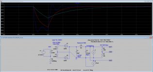
This sample shows the -almost- inadequate, the acceptable alternative and the -almost- exaggerated values of the (#45) SE amp's PSU last C value.
The load is 100msec pulse (0.2s-0.3s) of jump of current from steady value (47mA) to maximum value (94mA).
The acceptable recovery time response is return of B+ to 90% of steady value.
Seems "low" value (blue) producing swinging, the discharge is fast, the charging is begins during the "load", then at expiry begins some oscillation. The sag is significant.
The "acceptable" (red) shows balanced recharge/charge curve. The recovery time meets expectations, about 200msec. The sag is lower than previously, but not negligible.
The "exaggerated" (light blue) sag is better, but the recovery time is much larger.
You have to decide which alternative is better for given design, and better for you (listening).
No general "panacea".
IMHO the 1/10 assumption (without knowing the other parts of PSU and amp behaviour) is only assumption.
The value of "last C" depends of PSU construction, the amp requirements (structure, current behaviours etc.).
This sample shows the -almost- inadequate, the acceptable alternative and the -almost- exaggerated values of the (#45) SE amp's PSU last C value.
The load is 100msec pulse (0.2s-0.3s) of jump of current from steady value (47mA) to maximum value (94mA).
The acceptable recovery time response is return of B+ to 90% of steady value.
Seems "low" value (blue) producing swinging, the discharge is fast, the charging is begins during the "load", then at expiry begins some oscillation. The sag is significant.
The "acceptable" (red) shows balanced recharge/charge curve. The recovery time meets expectations, about 200msec. The sag is lower than previously, but not negligible.
The "exaggerated" (light blue) sag is better, but the recovery time is much larger.
You have to decide which alternative is better for given design, and better for you (listening).
No general "panacea".
Attachments
euro21: Thanks for the sim. It helps me understand. The iterative process as described in the Loesch article is similar to what you describe above. By all accounts, there isn’t a lot of need for precision...
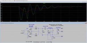
Feel like doing that sim with SS diodes instead? First cap 220uF? 😀
With small (30uF, 100uF) last capacitor it seems horrible. 🙂
300uF and above would be better ... with -at least- double recovery time.
BTW SS diode rectification requires different values (mainly choke), than tube rectification.
Attachments
Wow! I wasn't expecting that. What if L5 was 5R resistor, and C3 was 3300u? I'm guessing the bouce would go away?
But you're not modelling the OP's actual circuit, so your images are misleading.With small (30uF, 100uF) last capacitor it seems horrible. 🙂
"But you're not modelling the OP's actual circuit, so your images are misleading. "
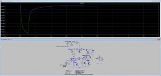
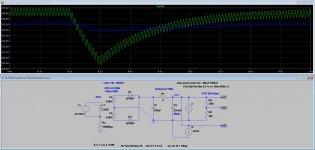
The original question was the last C value in #30 tube PSU chain.
The behaviour is the same.
I'm not sure, that (last C in #30 PSU chain, preceding 100uF-5k1-33uF-10k) 1.5uF or 30uF matters so much opposite the power tube's PSU chain quality.
The original question was the last C value in #30 tube PSU chain.
The behaviour is the same.
I'm not sure, that (last C in #30 PSU chain, preceding 100uF-5k1-33uF-10k) 1.5uF or 30uF matters so much opposite the power tube's PSU chain quality.
Attachments
Wow! I wasn't expecting that. What if L5 was 5R resistor, and C3 was 3300u? I'm guessing the bouce would go away?
Do you want few hundred mA charging pulses on last capacitor? :-o
"But you're not modelling the OP's actual circuit, so your images are misleading. "
The original question was the last C value in #30 tube PSU chain.
The behaviour is the same.
I'm not sure, that (last C in #30 PSU chain, preceding 100uF-5k1-33uF-10k) 1.5uF or 30uF matters so much opposite the power tube's PSU chain quality.
euro21: When I added a 33 uF cap to the 1.5 uF on the 30 tube power supply node, it didn’t make any audible difference to the sound. However, the speakers I use are La Scalas, and have a -3 DB point at around 57 Hz. I would imagine that the change would have been more obvious if my speakers went down to 20 Hz. The graphs really illustrate the impact of capacitor value changes on the recovery time/time constant and on the degree to which the cap is depleted on transients.
Please correct me if I’m wrong, but wouldn’t the sort of jump in current draw used in your sim never actually happen with a single ended amp?
"Please correct me if I’m wrong, but wouldn’t the sort of jump in current draw used in your sim never actually happen with a single ended amp? "
It's shows the PSU behaviour at worst case. If not swinging, the sag and the recovery not too much, would be good.
The correctly developed devices (sources, pre- and power amps) has LF bandwidth restrictions, so such stress does not usually occur.
But some electronic "music" may contains extreme sound effects, and -for example- footdrum punch also can cause surprises for SE amps.
- Home
- Amplifiers
- Tubes / Valves
- How do you size a capacitor for a B+ node?