In the absence of advice to the contrary, I am going to go ahead with a 3 stage amplifier / notch filter using the tle2141's. When I can I might replace the first stage with an ad797 for best noise performance.
Chances are this won't happen until next week, as it's the last few days of the school holidays and I'm spending some time with the kids before they go back to school. Also we have finally got some summer weather after 5 weeks of mostly rain!
Udo, thank you very much for directing me to the Samuel Groners opamp investigations. This is an excellent body of work and will almost certainly be useful to me when I get to designing my own amplifiers - that being my ultimate goal and reason for joining this website.
Last edited:
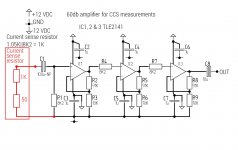
Managed to get a bit of spare time today. Built a three x 20db stages amplifier. Noise was reasonable except for 50Hz pickup. ( have been unable to implement Udo's notch filter as i only have 5% capacitors and my LCR meter has packed in, ruling out cherry picking from the 5% stock. ) I have an old biscuit tin and was thinking about putting the amplifier inside it to see if that helps with the 50Hz pickup.
The amplifier is all DC coupled except for the input ( as the CCS current sensing resistor will have a large DC component across it ) I was surprised to find that DC offset at the output was only 52mV and as I'll be coupling the meter via a capacitor. 52mV impact will have minimal impact on the dynamic range of the amplifier.
As for using the AD797 for the first stage, the manufacturer reckons it is not ideal for a 1K input source, there were other recommendations though ( Analog Devices parts of course! )
Gordon.
This is certainly interesting, a lot of information to digest, but it's certainly opened my eyes.
Any thoughts on using the TLE2141 as I think it's probably the best I have available for now?
Use the TL072 as it is now. It will work for your application. The TLE2141 will not improve things.
The critical opamp is the first for noise. Some good low noise op-amps are LME49990, AD797, LT1469 or NE5534.
Best,
Udo
Last edited:
What i want to add: it is more important to fix the problem with the 50 Hz crosstalk than to choose a better opamp.
I am very interested to hear if the cake-box helps against the crosstalk. A good reading is Henry Ott: Electromagnetic Compatibility
Engineering 2009 (you can find it online).
But beware: it is more fun to try things out and read the book later 🙂
I am very interested to hear if the cake-box helps against the crosstalk. A good reading is Henry Ott: Electromagnetic Compatibility
Engineering 2009 (you can find it online).
But beware: it is more fun to try things out and read the book later 🙂
What i want to add: it is more important to fix the problem with the 50 Hz crosstalk than to choose a better opamp.
I am very interested to hear if the cake-box helps against the crosstalk. A good reading is Henry Ott: Electromagnetic Compatibility
Engineering 2009 (you can find it online).
But beware: it is more fun to try things out and read the book later 🙂
Through trial and error I have eliminated most of the 50Hz, it was the result of the grounding arrangements. The metal box, connected to ground would probably still be a good idea. I have attached a schematic of the 3 stage amplifier. As you can see, no notch filter! I will get a better opamp for stage 1 next week probably. I've also been working on a precision rectifier, as I don't think my meter is accurate over 10Khz.
I will search for the book. I do have a book ( somewhere) that covers this type of stuff, also there is a good chapter in The Art of Electronics, Horowitz & Hill, 2nd edition
Thanks again for your input.
Attachments
Can you make photos of your new circuit and show what you have changed?
I (and many others) are very interested to see what you have changed so that the problem does not occcur anymore.
Have a look at the INA163 or similar instrumentation opamps. They could be a good
solution too for you measurement problem.
I (and many others) are very interested to see what you have changed so that the problem does not occcur anymore.
Have a look at the INA163 or similar instrumentation opamps. They could be a good
solution too for you measurement problem.
Last edited:
Feeling annoyed!😡
Spent awhile composing a detailed post only to be told "token has expired" and all was lost.
Brief summary: I have obtained a small aluminium flight case ideally sized to house my setup. Quick test showed a marked reduction in 50Hz interference when the apparatus was operated inside the case with the case connected to ground with the lid closed. I will need to drill suitable holes for connectors, etc.
Last night was reviewing opamp data sheets. Best choice would seem to be op37 or lt1128.
The op37 data sheet has a 3 opamp instrumentation amplifier with a gain of x1000. OP37 is somewhat cheaper than lt1128, which I could only find sold by LT direct through their website or dubious Chinese eBay sellers.
My 3 x tle2141 amplifier has a tendency to burst into oscillation at around 1Mhz when the scope probe is connected to the output. Would a 10 ohm resistor at the output help with this?
Photos will follow once things are looking a bit more presentable, yesterday I was working in a rats nest and it's a wonder that anything worked as it should, actually it didn't, for awhile but that's another story!
Gordon.
OP37 is the super high bandwidth, decompensated version of the OP27. OP37 is just barely stable / borderline unstable, for closed loop gains less than 5. Your design operates it at a closed loop gain of 10, awfully close to the Cliff Of Death.
Since your design only requires opamps with a bandwidth of 2MHz or so (20 kHz signal * 10x gain * 10x safety factor), why not use the OP27 instead, and bask in the supreme delight of enormous stability margin-of-safety? OP27's noise specs are just as good as OP37's.
_
Since your design only requires opamps with a bandwidth of 2MHz or so (20 kHz signal * 10x gain * 10x safety factor), why not use the OP27 instead, and bask in the supreme delight of enormous stability margin-of-safety? OP27's noise specs are just as good as OP37's.
_
Last edited:
Analog devices recommends the op37 for a 1K source impedance. I think it works out slightly quieter when you take current noise into account as well. I did think about the stability issue though, plus I think the op27 is slightly cheaper.
Some more remarks:
- Use 100 Ohm instead of 10 at the output. 10 Ohm is very low.
- Lower the feedback network impedance by a factor of 10 - 20.
Too much stray capacitance and noise!
You can then omit the series R at the + input too => even less noise.
- You think too much about the opamp and too less about the circuit. NE5532 (NE5534) is a bargain.
- If you need to go differential use a real instrumentation amp (ina163 etc.).
They do not use the 3-opamp circuit internaly and have less noise and less stability problems.
- if you omit the coupling C, choose a opamp with low i_bias and low Vos.
- If you still have substantial 50 Hz on the output it does not matter what opamp you choose.... but the instrumentation amp may help to suppres 50 Hz noise.
The ina163 is shown as a 3opamp internal structure.
For 2MHz you could increase the stage gain to ~ 30X (+30dB).
The ina163 would use 200r for Rg giving a stage gain of 6000/200 + 1
That leaves the possibility of needing just one more stage for your +60dB
For 2MHz you could increase the stage gain to ~ 30X (+30dB).
The ina163 would use 200r for Rg giving a stage gain of 6000/200 + 1
That leaves the possibility of needing just one more stage for your +60dB
If the ina163 would use the 3-opamp structure it would through away 3 dB of noise AND some silicon area.
Look up the datasheet of SSM2019 to see some details how these chips really work.
The 3-opamp structure is only a very simple explanation for the application engineer to stop him from asking more questions...
Look up the datasheet of SSM2019 to see some details how these chips really work.
The 3-opamp structure is only a very simple explanation for the application engineer to stop him from asking more questions...
If the ina163 would use the 3-opamp structure it would through away 3 dB of noise AND some silicon area.
Look up the datasheet of SSM2019 to see some details how these chips really work.
The 3-opamp structure is only a very simple explanation for the application engineer to stop him from asking more questions...
Like a lot of the "equivalent" schematics that you often see in data sheets, I presume?
I could only find the ina163 in SMT now and with my shaky hands smt parts are out of the question!
I have taken onboard some of Udos comments. I have:
1. Changed the first stage to ne5534
2. Scaled down the feedback network to 10K & 1K1 on the first two stages.
3. Because there was ~ 1 volt DC offset at the output, i have switched to capacitive coupling between stages. The DC offset is now only 12mV.
With these changes and the aforementioned aluminium case, the noise level including 50Hz pickup is now much lower.
I expect to be posting some results soon. Though there seems to be a problem with my signal generator at lower frequencies ( the amplitude is unstable ) and it makes taking accurate measurements difficult. I need to try and find the manual as it has a schematic diagram of the unit. Couldn't find one online that included the diagram.
Gordon.
p.s. I actually have an ina131 instrumentation amplifier, but its input noise is quite a bit higher than that of the ne5534 and the aluminium box seems to be taking care of most of the 50Hz interference, so don't think that a differential input will be necessary.
Don't forget the NE5534 offset compensation pin 🙂
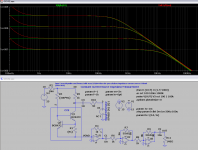
Yeah, I forgot which pins to connect the capacitor across, so I added a 330p capacitor in parallel with the 10k feedback resistor as the ne5534 was bursting into oscillation. The capacitor cured this. I have measured the gain of the setup using a 50M resistor (measures as 50.23M), have taken note of the frequency response at 10Khz it is down about 1.9db, this seems to be more to do with wiring and terminal blocks, as the amplifier itself ( assembled on a breadboard ) is flat to within 0.1db over 100Hz-10Khz.
Another oddity is an unexplained peak in the impedance when measuring the same 2 transistor 1mA CCS. The problem I think must lie in construction problems. Originally I had the CCS assembled on a breadboard, but was concerned with stray capacitive coupling, so moved it to a plastic terminal block. There is also noise getting into the signal path from the bench power supply that powers the CCS. The amplifier has its own +/-12 volt supply.
I have measured 75M approx with the 2 transistor CCS at 50 & 100 Hz, but not sure how accurate this is yet.
To measure higher than this, other measures will need to be considered.
Gordon.
If the ina163 would use the 3-opamp structure it would through away 3 dB of noise AND some silicon area.
Look up the datasheet of SSM2019 to see some details how these chips really work.
The 3-opamp structure is only a very simple explanation for the application engineer to stop him from asking more questions...
Thanks Udo, I looked at the ssm2019 data sheet and it would seem that it is better suited to very low source impedances as the current noise is relatively high @2pA/√Hz so would add 2nV/√Hz with a 1K source. In that respect the ne5534 is superior, but has a higher voltage noise at 4nV/√Hz. However when you calculate √(En^2+In^2), the ssm2019 works out better at 2.236nV/√Hz compared with 4.031nV/√Hz for the ne5534, this does not include the thermal noise contributed by the resistors.
Gordon.
Attached a variation with inverting opamp configuration.
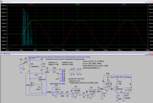
The CCS cold end is at virtual ground and noise is suprisingly somewhat better than the noninverting configuration.
Shown are the Impedance of the current source for 100uA,300uA,1mA and 3mA (calculated and "measured" at V(out)).
With the 5534/5532 noise is dominated by the current source, so there is no
need for further optimizations.
Attachments
Attached a variation with inverting opamp configuration.
The CCS cold end is at virtual ground and noise is suprisingly somewhat better than the noninverting configuration.
Shown are the Impedance of the current source for 100uA,300uA,1mA and 3mA (calculated and "measured" at V(out)).
With the 5534/5532 noise is dominated by the current source, so there is no
need for further optimizations.
Someone else I know had suggested the trans impedance amplifier idea but I thought the DC component would be a problem, but making the first stage 1v per mA allows for an acceptable level of DC offset at the output of stage 1.
It occurred to me too that some noise was coming from the current source itself as the output noise was higher when amplifying the CCS signal rather than just the signal generator via an attenuator. Perhaps this is another current source characteristic worth exploring, given that the target is to find CCS' suitable for audio.
____________________________________
A version with a peak detector added. This should help with measuring
at higher precision above 1kHz.
By making R4 switchable (1k or 10k) you can improve accuracy for low current measurments.
If I used 2 x TL-071, i could correct offset if this is a problem. Is the choice of transistor crucial? I seen a circuit like this that used a jfet junction as the rectifier.
Gordon.
Last edited:
- Status
- Not open for further replies.
- Home
- Amplifiers
- Solid State
- How do you calculate impedance of a current source?