The ones before the op amp have been removed.ninjanki said:What you are saying is that we actually need four capacitors for coupling modding? Because I understood that there are two of those before the op-amp.
As all components on the UCD modules are individually numbered may I propose that you include this info into your comments. Makes things better understandable, at least for me.
So Jan-Peters last statement would read:
"For modding you can always mount them on the bottom side of the pcb....
Just an idee...
All current UcD modules has the coupling caps Cxx and Cxx BETWEEN the op amp and modulator!"
Thank you
Wilfried
So Jan-Peters last statement would read:
"For modding you can always mount them on the bottom side of the pcb....
Just an idee...
All current UcD modules has the coupling caps Cxx and Cxx BETWEEN the op amp and modulator!"
Thank you
Wilfried
Coupling caps
Jan-Peter
Now I am really confused. I thought all the new modules with jfet opamps had only input caps to these opamps and not output ones. Is the 400AD module different?
I agree we should use reference designators to avoid confusion.
Roger
Jan-Peter
Now I am really confused. I thought all the new modules with jfet opamps had only input caps to these opamps and not output ones.
Is the 400AD module different?I agree we should use reference designators to avoid confusion.
Roger
All current modules has the coupling cap's BETWEEN the op amp and modulator.
For modding this is actually not interesting, you can still short circuit the coupling caps or even remove them. In this case you have a full dc coupling. However this is only possible in the UcD180AD, UcD400ST and UcD400AD. Of course you have to be VERY carefully with DC at the input!
If you like to use a better coupling cap, do the above mention procedure and mount the better coupling (and can be lower in value!!) in series with the both symmetrical 4-pins connector.
Good luck!
Cheers,
Jan-Peter
Jan-Peter,
I looked at my modules, and both modules have two 22uF/50V (C23 and C24)capacitors between the signal pins and the AD OP-AMP. If i am understanding it correctly, that means they are positioned before the op-amp. There are also another two of those capacitors(C29-C28), on the other side of the module, but I am not sure what they are used for. My S/N is 509, UCD400 - AD8620. Maybe my version of the modules is not the final one, and that's why my observations are not matching your statements...
Anyway, how effective is DC coupling after the op-amp. Doesn't it leave the Op-Amp unprotected? Or even worse, couldn't it permit the clipping of the op-amp output in extreme DC cases?
Allan
Originally posted by Ninjanki;
I looked at my modules, and both modules have two 22uF/50V (C23 and C24)capacitors between the signal pins and the AD OP-AMP. If i am understanding it correctly, that means they are positioned before the op-amp. There are also another two of those capacitors(C29-C28), on the other side of the module, but I am not sure what they are used for. My S/N is 509, UCD400 - AD8620. Maybe my version of the modules is not the final one, and that's why my observations are not matching your statements...
Anyway, how effective is DC coupling after the op-amp. Doesn't it leave the Op-Amp unprotected? Or even worse, couldn't it permit the clipping of the op-amp output in extreme DC cases?
In your version this is BEFORE the op amp, the change in version is done several weeks ago. The C28-C29 are decoupling caps for the +12V/-12V.
The function is the same for or after the op amp, after the op amp you have less DC offset at the output. Because the DC offset of the op amp is blocked by the coupling caps.
Cheers,
Jan-Peter
PS.....yes the FAQ, I am looking forward to that...
Jan-Peter said:PS.....yes the FAQ, I am looking forward to that...
Point taken, JP, point taken. 🙂
Faq!
FAQ, YES, YES, we won't be answering the same questions over and over! Also some info on changes made at different serial numbers would be very helpful. Like a revision list as follows;
From SN “X” to “Y” cap C24 = 22uf, SN “Y” and up it is removed.
Some separate headings I would like to see;
DC protection
On/off circuits/connections/switches
Power supply issues, including storage caps
Cap issues (all)
Mounting and heat sink issues
Mechanical drawing for mounting holes along with spacing requirements
Drawings for different input configurations
Power and output wiring issues
Feel free to add more!
Roger
Bruno Putzeys said:
The ones before the op amp have been removed.
So we are back at the situation with the first UcD180 modules (the ones I have that had the coupling caps between opamp and UcD).
My 400s have them before the opamp, but I removed them.
Best regards
Gertjan
Yes, the reason was that one OEM customer had a strange output stage topology on their signal processing board, which resulted in pop noises if the cap was placed at the input. Sometimes one has to select the option which is most "bomb proof".ghemink said:So we are back at the situation with the first UcD180 modules (the ones I have that had the coupling caps between opamp and UcD).
Pop noise
Bruno,
Did you investigate the problem at any length? Just wondering if it could have to do with a too long of time constant, 22uf and 100k is real long. Going from 100k to 1.8k shortens it up quite a bit. As always, the customers use is the real worst case test. It does seem a shame to have to make changes to cover one case like this.
Roger
Re: Pop noise
The problem is worse than that. Customer set his output high-Z at startup, which means that the caps never got to discharge at all. Admittedly, we'd have covered this case quite well by installing resistors to ground not only after, but also before the coupling caps, and then set the time constant short enough. It's just that one can never be sure what people can stuff up next.
On the other hand, by placing the caps after the op amp, we know for sure what the impedance will be on either end at all times.
The only thing I can do is tell diy enthousiasts to short out the on-board caps and add better ones at the input (if at all necessary).
sx881663 said:Bruno,
Did you investigate the problem at any length? Just wondering if it could have to do with a too long of time constant, 22uf and 100k is real long. Going from 100k to 1.8k shortens it up quite a bit. As always, the customers use is the real worst case test. It does seem a shame to have to make changes to cover one case like this.
Roger
The problem is worse than that. Customer set his output high-Z at startup, which means that the caps never got to discharge at all. Admittedly, we'd have covered this case quite well by installing resistors to ground not only after, but also before the coupling caps, and then set the time constant short enough. It's just that one can never be sure what people can stuff up next.
On the other hand, by placing the caps after the op amp, we know for sure what the impedance will be on either end at all times.
The only thing I can do is tell diy enthousiasts to short out the on-board caps and add better ones at the input (if at all necessary).
Typical Problems
Yes, reminds me of designing an amp that can handle a speaker that dips to 1 ohm or less. One never knows what odd ball stuff will get connected to our products. The only thing for sure is that it will always be worse than we can imagine.
To those of us that will mod our amps it makes no practical difference as you stated. The only thing we do worry about when you change something like this is if it is something we also should change. In this case obviously no. I would like to think the design is mature enough that this won’t happen but I realize it is new technology and I am sure there will be surprises.
We sure are getting off topic here. To get back on track I am going to be replacing the 470uf caps on my modules with much larger ones. I will be using regulated supplies so am opting for 63 volt units that will be at 59-60 volts. These are about the lowest ESR units I could find (around 7 millohm). Do you think there will be a problem with ringing? If so would an RC snubber suffice, thinking of something like .22uf and .2 ohm?
Roger
Re: Typical Problems
I think the maturity of the technology does not come into question here. This is simple, analogue opamp resistor and cap stuff. The problem has nothing to do with class D operation. This is what has puzzled me a lot while I was at Philips. Most of the time I was fixing problems in customers' op amp circuits, stuff that had absolutely nothing to do with the amplifier that was used. What happens is that before, when they made their own power amplifiers (linear), all problems were clearly their own, and they had to solve them all by themselves. Enter an amplifier bought from somewhere else. They design a new product, make all the same mistakes again but now they'll think each and every problem is caused by the amplifier.
So on monday morning you get this chap on the phone "Su', we have a probrem wih hum on yo' ampurifaia modure. Can you prease fix?" You have them fedex over a model and on wednesday you begin by disconnecting the amplifier, knowing full well that it's not going to be the cause of the problem.
Indeed, out of the line level connector come hum, noise, distortion and pop noises galore and you spend the next week correcting the most screamingly obvious mistakes. You send the whole thing back with a 25 page letter explaining basic electronics. They don't blush and they don't say thank you.
It is a mystery how these chaps managed before they had suppliers of unrelated material to lean on.
Worse still, this is becoming an established business model, more specifically with customers in the world's most populous country. Semiconductor vendors are now actively put under pressure by customers do develop and/or debug their products, otherwise no sales (because no product to put them in).
sx881663 said:I would like to think the design is mature enough that this won’t happen but I realize it is new technology.
I think the maturity of the technology does not come into question here. This is simple, analogue opamp resistor and cap stuff. The problem has nothing to do with class D operation. This is what has puzzled me a lot while I was at Philips. Most of the time I was fixing problems in customers' op amp circuits, stuff that had absolutely nothing to do with the amplifier that was used. What happens is that before, when they made their own power amplifiers (linear), all problems were clearly their own, and they had to solve them all by themselves. Enter an amplifier bought from somewhere else. They design a new product, make all the same mistakes again but now they'll think each and every problem is caused by the amplifier.
So on monday morning you get this chap on the phone "Su', we have a probrem wih hum on yo' ampurifaia modure. Can you prease fix?" You have them fedex over a model and on wednesday you begin by disconnecting the amplifier, knowing full well that it's not going to be the cause of the problem.
Indeed, out of the line level connector come hum, noise, distortion and pop noises galore and you spend the next week correcting the most screamingly obvious mistakes. You send the whole thing back with a 25 page letter explaining basic electronics. They don't blush and they don't say thank you.
It is a mystery how these chaps managed before they had suppliers of unrelated material to lean on.
Worse still, this is becoming an established business model, more specifically with customers in the world's most populous country. Semiconductor vendors are now actively put under pressure by customers do develop and/or debug their products, otherwise no sales (because no product to put them in).
Jan-Peter said:All current modules has the coupling cap's BETWEEN the op amp and modulator.
For modding this is actually not interesting, you can still short circuit the coupling caps or even remove them. In this case you have a full dc coupling. However this is only possible in the UcD180AD, UcD400ST and UcD400AD. Of course you have to be VERY carefully with DC at the input!
If you like to use a better coupling cap, do the above mention procedure and mount the better coupling (and can be lower in value!!) in series with the both symmetrical 4-pins connector.
Good luck!
Cheers,
Jan-Peter
Hi Jan-Peter and Bruno,
I'm still a little confused about the coupling cap between the op-amp and modulator.
Could you please indicate which one it is.
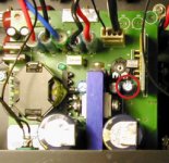
I'm looking at some pictures of my UcD400AD modules and I'm inclined to guess it is the lonely small black elctrolytic cap between the "daughter card" and blue heat transfer "T". Or is the coupling cap surfaced mounted under the board?
I've made a red circle around the cap I think is the coupling cap in the attached photo.
If my module input has no DC going to it, is it safe to bypass this cap as well?
Thanks.
Attachments
You have removed the coupling caps......😀
The couling caps are C23 and C24 in all types!
In your version they are place before the op amp.
Jan-Peter
The couling caps are C23 and C24 in all types!
In your version they are place before the op amp.
Jan-Peter
Since you're addressing both of us I still owe you an answer 😀Julien_M said:Hi Jan-Peter and Bruno,
I'm still a little confused about the coupling cap between the op-amp and modulator.
Could you please indicate which one it is.
I'm looking at some pictures of my UcD400AD modules and I'm inclined to guess it is the lonely small black elctrolytic cap between the "daughter card" and blue heat transfer "T". Or is the coupling cap surfaced mounted under the board?
I've made a red circle around the cap I think is the coupling cap in the attached photo.
If my module input has no DC going to it, is it safe to bypass this cap as well?
Thanks.
There are only 2 coupling caps on the modules. On one generation they're before the op amp, on the new generation they're after the op amp. You've already removed all coupling caps there are on your module.
The cap that you've encircled is the bootstrap capacitor. The module will not work very well without it

Jan-Peter said:You have removed the coupling caps......😀
The couling caps are C23 and C24 in all types!
In your version they are place before the op amp.
Jan-Peter
Bruno Putzeys said:
Since you're addressing both of us I still owe you an answer 😀
There are only 2 coupling caps on the modules. On one generation they're before the op amp, on the new generation they're after the op amp. You've already removed all coupling caps there are on your module.
The cap that you've encircled is the bootstrap capacitor. The module will not work very well without it
Thank you both for the prompt reply. Now everything make sense.
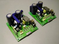
As you might have noticed from my pictures I also replaced the main supply caps and the low voltage decoupling caps with Panasonic FC caps. That brought a big change in sound, I feel the caps are still breaking in so I haven't commented on the sound yet, but the overall presentation is smoother and more natural. More tube like...
Bruno, is the quality of the bootstrap capacitor critical to the sound? Do you think it could be improved upon?
Attachments
Not very. The difference is noticeable but slight.Julien_M said:Bruno, is the quality of the bootstrap capacitor critical to the sound?
- Status
- Not open for further replies.
- Home
- Amplifiers
- Class D
- Hotrodding the UCD modules