The "correct" value should be 1.463.
Strictly speaking, the flanged plus unflanged end correction factor should be 1.462 (a dimensionless value).
Flanged end correction factor = 8 / (3 * Pi)
Unflanged end correction factor = 0.1952 * Pi
Flanged plus unflanged end correction factors to three decimal places = 1.462
Using 1.462 in your test example gives Lpt = 90.15 cm.
Hornresp then calculates Fb to be exactly 30 Hz 🙂.
Should cf perhaps be called vent volume correction, rather than vent length correction?
Of course, both the "new" equation AND Hornresp could be wrong about the predicted Fb for a volume Vb tuned by a tube of area Ap and length Lpt.
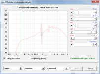
Hornresp should be reasonably accurate as it predicts the resonance frequency based on the actual simulated performance of the system, not by using a relatively simple formula. Attachments 2 and 3 refer.
Attachments


total = 50 different situations.
Should that be 43 different situations?
Varying Fb from 20Hz to 100Hz in 10Hz increments gives 9 not 10 samples.
1 * 10 + 4 * 9 - 3 duplications = 43 🙂
and the LDC itself might be wrong, at least where it quoted that particular equation (in the section concerning 4th order BP systems).
Good pickup, it certainly seems that way.
Not that it will make much difference but I will probably change the value used in the BP4 design tool vent length formula from 1.595 to 1.462.
Thanks David. I updated my spreadsheet to use 1.462 for the vent end-correction, and I updated the value for K to, to be a closer match to the value used in the common equation. Using a value of 0.30 now for the "vent volume correction" seems to work well. Not perfect, but it seems to produce results that are very close to the Hornresp sim predictions for Fb.
However, this only fudges the standard equation to produce a result that's much closer to that predicted by an equivalent Hornresp sim.
What it doesn't do is produce a result that's backed up by measurements of an actual build. I've found one page so far that tests the calculated value for Lpt against actual Lpt for a given Vb, Fb combo, and the observations suggest that the calculated value for Lpt might be off by as much as 19%. See http://troelsgravesen.dk/vent_tuning.htm
I might have to just build my own test box to confirm those findings.
| Metric | Imperial | Conv. | Check | |||||||
| c | = | 344.0 | m/s | 1128.6 | ft/s | = | 344.0 | m/s | 0.0 | |
| k | = | 274.496 | 12962.886 | |||||||
| ec1 | = | 0.849 | vent end correction (flanged) | 0.849 | ||||||
| ec2 | = | 0.613 | vent end correction (free) | 0.613 | ||||||
| ec | = | 1.462 | total vent end correction (flanged + free) | 1.462 | ||||||
| cf | = | 0.300 | vent length correction | 0.300 | ||||||
| Vb | = | 60.0 | litres | Box Volume | 3659.9 | cu.in. | = | 60.0 | litres | 0.0 |
| Lb | = | 25.0 | cm | 9.8 | in | = | 25.0 | cm | 0.0 | |
| Ab | = | 2400.0 | cm^2 | 372.0 | sq.in | = | 2400.0 | cm^2 | 0.0 | |
| Ap | = | 330.0 | cm^2 | Vent Area | 51.2 | in.^2 | = | 330.0 | cm^2 | 0.0 |
| Fb | = | 30.0 | Hz | Target Resonance Frequency | 30 | Hz | ||||
| D | = | 20.5 | cm | D=2*(Ap/PI())^0.5 | 8.1 | in. | = | 20.5 | cm | 0.0 |
| R | = | 10.2 | cm | R=D/2 | 4.0 | in. | = | 10.2 | cm | 0.0 |
| K | = | 94426.7 | K=k*c | 14630000 | ||||||
| Lpt' | = | 168.7 | cm | Lpt'=(k*c*R^2/(Fb^2*Vb))-ec*R | 66.4 | in. | = | 168.7 | cm | 0.0 |
| Vp | = | 55.7 | litres | Vp=Ap*Lpt'/1000 | 3397.2 | cu.in. | = | 55.7 | litres | 0.0 |
| Vb' | = | 76.7 | litres | Vb'=Vb+cf*Vp | 4679.1 | cu.in. | = | 76.7 | litres | 0.0 |
| Lpt | = | 128.7 | cm | Lpt=(k*c*R^2/(Fb^2*Vb'))-ec*R | 50.7 | in. | = | 128.7 | cm | 0.0 |
However, this only fudges the standard equation to produce a result that's much closer to that predicted by an equivalent Hornresp sim.
What it doesn't do is produce a result that's backed up by measurements of an actual build. I've found one page so far that tests the calculated value for Lpt against actual Lpt for a given Vb, Fb combo, and the observations suggest that the calculated value for Lpt might be off by as much as 19%. See http://troelsgravesen.dk/vent_tuning.htm
I might have to just build my own test box to confirm those findings.
Attachments
Never said it was 10Hz step. I said that I did 10 simulations between 20 and 100Hz for each chosen volume.Should that be 43 different situations?
Varying Fb from 20Hz to 100Hz in 10Hz increments gives 9 not 10 samples.
1 * 10 + 4 * 9 - 3 duplications = 43 🙂
I redid your test and the result of my formula is:Just one test...
Given:
Vb =100 litres
fb = 50 Hz
Ap = 25 cm^2 (port cross-sectional area assumed for the purposes of the test)
Vb = 6102.37 inches^3
R = 2.22 inches
Lv = 1.39 inches
Vp = 5.40 inches^3
Lpt = 1.48 inches = 3.75 cm
Using the values of Vb, Ap and Lpt (in cm) as inputs, Hornresp calculates the resonance frequency to be 30.8 Hz when the design frequency is 50 Hz.
Vb=100 Liters
Fb = 30.8Hz
Lv = 3.91cm
Difference of 0,16cm or 0,3Hz.
Difference is not significant.
Did you like the results?I tried your method, but I seem to get better results by dividing Vp by 3 in the equation to find the final value for Lp. I used the vent design equation from the LDC and kept all parameters metric for easier understanding. See example below.
D = cm Ap = cm^2 Vb = litres Fb = Hz Lp1 = cm Lp1=(9.425*10^4*(D/2)^2/(Fb^2*Vb))-1.595*(D/2) Vp = litres cf = Lp = cm Lp=(9.425*10^4*(D/2)^2/(Fb^2*(Vb+cf*Vp)))-1.595*(D/2) Vt = litres
You can't imagine how happy I am to receive your endorsement on my formula for port length! From Brazil, thank you very much!Just to confirm, I assume that the formulas to actually use are as shown below, and that the original 5.5 constant has been changed to 5.6?
(The operators missing from your equation have been added in red).
For Step 1:
Lv1 = (274.419*C)x((D/2)x2.54)^2/((Fb^2)xVb)-Ecx((D/2)*2.54)
For Step 2:
Lv2 = (274.419*C)x((D/2)x2.54)^2/((Fb^2)x(Vb+Vp/5.6))-Ecx((D/2)*2.54)
If so, then for the small amount of testing I have done the method appears to be surprisingly accurate when Fb, Vb and D have realistic values.
Maybe the method should be added to Hornresp as a bass reflex loudspeaker design tool…🙂
Well done!
Re: "Lp1=(9.425*10^4*(D/2)^2/(Fb^2*Vb))-1.595*(D/2)"
Turns out that the "1.595" factor for the end correction calculation in the LDC (mentioned in the section covering 4th order bandpass enclosures) might actually be incorrect.
Turns out that the "1.595" factor for the end correction calculation in the LDC (mentioned in the section covering 4th order bandpass enclosures) might actually be incorrect.
kkkkkkk"Build" = "Design the box and get someone else to build it for me so I can chastise them about their box-building skills"...
Hello David,
I hope you doing well.
I'm about to finish my vocation and I took some days to do things for myself, including the Hornresp CH3 model evaluation that you implemented in order to evaluate different possible layouts as I suggested back in that time.
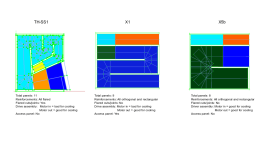
Attached you can find a PDF and ZIP file with all Hornresp inputdata in order to compare different layouts, it's also attached two images that shown the best layout I found witch is the model X5b. It seems very promising in terms of the simplicity to build, cooling capacity and delivered SPL/band. The only downside I found was higher group delay at tuned frequency, it may require additional investigation to mitigate it.
The objective was to find good directions in order to justify or not further analysis from me or any interested users. For all models I tested different driver positions until finding a good spot. But take into account that I didn't made fine tuning for any spec, so there are some small differences that at this stage, from my point of view, are not important.
Best regards,
Marcelo
I hope you doing well.
I'm about to finish my vocation and I took some days to do things for myself, including the Hornresp CH3 model evaluation that you implemented in order to evaluate different possible layouts as I suggested back in that time.
Attached you can find a PDF and ZIP file with all Hornresp inputdata in order to compare different layouts, it's also attached two images that shown the best layout I found witch is the model X5b. It seems very promising in terms of the simplicity to build, cooling capacity and delivered SPL/band. The only downside I found was higher group delay at tuned frequency, it may require additional investigation to mitigate it.
The objective was to find good directions in order to justify or not further analysis from me or any interested users. For all models I tested different driver positions until finding a good spot. But take into account that I didn't made fine tuning for any spec, so there are some small differences that at this stage, from my point of view, are not important.
Best regards,
Marcelo
Attachments
I updated my spreadsheet to use 1.462 for the vent end-correction, and I updated the value for K to, to be a closer match to the value used in the common equation. Using a value of 0.30 now for the "vent volume correction" seems to work well.
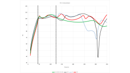
From the testing I have done it would seem that in most cases your results are marginally more accurate, but that overall the model is not quite as robust as the one developed by Sea-Sky.
Try these examples:
fb = 40 Hz
Vb =30 litres
Ap = 81 cm^2
fb = 40 Hz
Vb =100 litres
Ap = 81 cm^2
I've found one page so far that tests the calculated value for Lpt against actual Lpt for a given Vb, Fb combo, and the observations suggest that the calculated value for Lpt might be off by as much as 19%.
It is interesting that given box volume, vent diameter and vent tube length, the ratio of actual tuning frequency to the Hornresp predicted frequency is pretty constant at around 0.9.
Never said it was 10Hz step. I said that I did 10 simulations between 20 and 100Hz for each chosen volume.
I thought that I had checked your method against all the situations listed in Post #13,776, but apparently not. Out of interest, what were the 10 frequencies used between 20 Hz and 100 Hz?
I redid your test and the result of my formula is:
Vb=100 Liters
Fb = 30.8Hz
Lv = 3.91cm
Difference of 0,16cm or 0,3Hz.
Difference is not significant.
My original test used the formulas exactly as you gave them in Post #13,763. They were the latest ones that you had posted up until that time. As it turns out, the second formula contained an error:
Vb*(Vp/5.5) should have been (Vb+Vp/5.5)
Just to check, does your latest formula use the following values?
C = 346
274.419 * C
Vp/5.6
Ec = 1.464
Turns out that the "1.595" factor for the end correction calculation in the LDC (mentioned in the section covering 4th order bandpass enclosures) might actually be incorrect.
As you surmised earlier in Post #13,800 🙂.
Attached you can find a PDF and ZIP file with all Hornresp inputdata in order to compare different layouts, it's also attached two images that shown the best layout I found witch is the model X5b.
Hi Marcelo,
Very interesting indeed. Many thanks for the comprehensive feedback!
Kind regards,
David
Very interesting indeed
Hello again David,
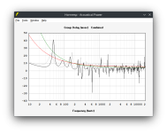
Would it be possible for you to check the X5b simulation and give me some tip/foot print regarding the high group delay value around tuning frequency?
The involved horn length is shorter compared to the Tapped Horn I used in the comparison so I think it may not be trivial to understand what is happening. The amplitude is almost twice higher.
X5b: Front Horn = 83,5cm Back horn = 161,7cm GD = 41ms@49Hz
TH-SS1: Horn = 241,4cm GD = 23ms@43Hz
Attached there is the inputdata and Hornresp Group Delay Comparison screenshot.
Regards,
Marcelo
Attachments
From the testing I have done it would seem that in most cases your results are marginally more accurate, but that overall the model is not quite as robust as the one developed by Sea-Sky.
Try these examples:
fb = 40 Hz
Vb =30 litres
Ap = 81 cm^2
fb = 40 Hz
Vb =100 litres
Ap = 81 cm^2
| Vb | Fb | Vp/Vt | original | modified | sim (orig.) | sim (mod.) |
| 30 | 40 | 0.12 | 43.3 | 41.6 | 38.9 Hz | 39.5 Hz |
| 100 | 40 | 0.01 | 7.8 | 7.8 | 39.5 Hz | 39.5 Hz |
The results don't look too bad. Pretty decent in fact. They also suggest that Lpt predicted by the standard equation starts noticeably deviating from what's actually required when Vp/Vt is as low as 10%. In fact, with a bit of trial and error, I noticed noticeable deviation with Vp/Vpt as low as 5%. I'll bet that this puts it in range of almost every modern-day vented subwoofer alignment...
Sea-Sky's equation uses slightly different values for c and for the constants, so it will produce slightly different results. In my equations, I tried to keep those values as close as possible to published values and values used in Hornresp. Would be kind of difficult to justify using 346 m/s for c in the fudged equation and compare its results to a Hornresp sim which uses 344 m/s instead... 🙂.
It is interesting that given box volume, vent diameter and vent tube length, the ratio of actual tuning frequency to the Hornresp predicted frequency is pretty constant at around 0.9.
View attachment 1203373
Yup. It does suggest that there's a "global constant" that relates predicted Fb to actual Fb. Unfortunately, there's only five measurements involved here, not really enough to draw any significant conclusions about the issue.
- Home
- Loudspeakers
- Subwoofers
- Hornresp