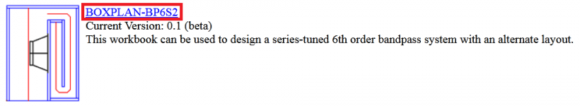
1. Go to my sheets site, and download the BOXPLAN-BP6S2 workbook
Hi Brian,
I cannot download the BOXPLAN-BP6S2 workbook for some reason. Clicking on the link (highlighted in the attachment) simply takes me back to your Home Page.
Kind regards,
David
Attachments
Fixed... 🙂
That's better 🙂.
2. Open the BOXPLAN workbook and on the "Design" sheet, set target S4 to 900 cm^2 and select "Export!"
There is no S4 - do you perhaps mean Ap1?
I have now found the problem, Brian - it will be fixed in the next update, hopefully to be released on Friday. Thanks for the feedback.
Feature request - Porous/leaky enclosures and horn sections
Hello David,
Is it feasible to allow for porous walls, in order to model cadioids such as these models from kimmosaunisto?
Hello David,
Is it feasible to allow for porous walls, in order to model cadioids such as these models from kimmosaunisto?
Attachments

Good we have AHAG here in the forum.
(anonymous hornresp addicts group)
I have been thinking about this to.
It should be fairly straightforward all the basics are already there. But that's up to Master McBean.
I have been thinking about this type of a design for about 8 years. Time to move ahead with it
I have been thinking about this to.
It should be fairly straightforward all the basics are already there. But that's up to Master McBean.
I have been thinking about this type of a design for about 8 years. Time to move ahead with it
no more thinking. You can pave the road or clear the way for it. Either way youre the bossman👍🏻 If referring to the segments used to support the harmonic fractions / intervals of the Fb, and offset stubs or tapped at a midpoint with two folds to break into the layers of Fb as ‘halfwave’ function at the end? Or anything thats familiar to those?? I want the apprenticeship spot if available!!
Im teetering on WTH? And OMG? And Its along long journey to find the tiny bits i dont even quite have as a treasure map😱
Oh don't get your knickers in too tight of a knot.
The fundamental tools are there in Hornresp. Where we can put the stuffing is not quite as flexible as it might be. My guess, is Master McBean would be able to do it in a canned setup similar to the input wizard settings. That could constrain the possible entries and cause less problems.
I'm pretty good at working with Hornresp. But there are guys on this forum that I canna hold a candle to captin.
Is it feasible to allow for porous walls, in order to model cadioids such as these models from kimmosaunisto?
Hi Giri,
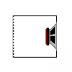
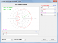
The system shown in Attachment 1 can be simulated in Hornresp.
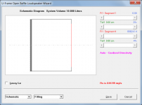
The model should be specified as documented in the red highlighted section of Attachment 2.
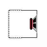
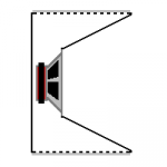
The other three systems cannot be simulated in Hornresp.
Kind regards,
David
Attachments

Oh don't get your knickers in too tight of a knot.
The fundamental tools are there in Hornresp. Where we can put the stuffing is not quite as flexible as it might be. My guess, is Master McBean would be able to do it in a canned setup similar to the input wizard settings. That could constrain the possible entries and cause less problems.
I'm pretty good at working with Hornresp. But there are guys on this forum that I canna hold a candle to captin.
One area thats completely stuff able throughout is CH1. a lot of things in that sim to do and stuffing on both sides of the cone to play with .
Hornresp Update 5120-210101
Hi Everyone,
CHANGE 1
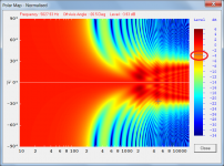
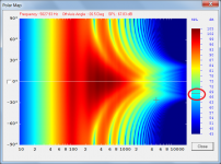
The decibel scales on the Impulse Spectrogram and Polar Map now have a marker line showing the sampled level. Attachments 1 to 3 refer.
CHANGE 2
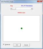
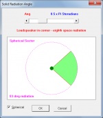
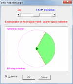
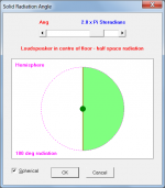
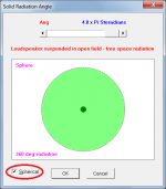
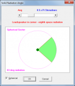
The Solid Radiation Angle input form now has a Spherical option which shows the loudspeaker radiating into a sphere, hemisphere or spherical sector. The radiation angle is given in degrees. Attachments 4 to 8 refer.
CHANGE 3
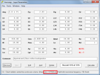
When the mouse pointer is moved over the Vrc or Lrc label or input box, the cross-sectional area Arc of the rear chamber is now shown in the status bar panel at the bottom of the Input Parameters window. Attachment 9 refers.
CHANGE 4
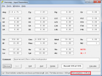
When the mouse pointer is moved over the Lpt label or input box in a bass reflex system, the internal port tube end correction value used when calculating the results is now shown in the status bar panel at the bottom of the Input Parameters window. Attachment 10 refers.
CHANGE 5
Several other minor operational "loose ends" have also now been tidied up. (They were not affecting the accuracy of the simulation results).
BUG FIX 1
For offset driver and tapped horn systems, the Save command button in the Loudspeaker Wizard was not being enabled when a length slider value was changed by clicking on the arrow at either end of the slider bar. This bug has now been fixed.
My thanks to camplo for reporting the problem.
BUG FIX 2
Ap1 and Ap2 cross-sectional areas imported into Hornresp from BOXPLAN band pass workbooks were being limited to a maximum value of 999.99. This bug has now been fixed.
My thanks to Brian for reporting the problem.
Kind regards,
David
Hi Everyone,
CHANGE 1
The decibel scales on the Impulse Spectrogram and Polar Map now have a marker line showing the sampled level. Attachments 1 to 3 refer.
CHANGE 2
The Solid Radiation Angle input form now has a Spherical option which shows the loudspeaker radiating into a sphere, hemisphere or spherical sector. The radiation angle is given in degrees. Attachments 4 to 8 refer.
CHANGE 3
When the mouse pointer is moved over the Vrc or Lrc label or input box, the cross-sectional area Arc of the rear chamber is now shown in the status bar panel at the bottom of the Input Parameters window. Attachment 9 refers.
CHANGE 4
When the mouse pointer is moved over the Lpt label or input box in a bass reflex system, the internal port tube end correction value used when calculating the results is now shown in the status bar panel at the bottom of the Input Parameters window. Attachment 10 refers.
CHANGE 5
Several other minor operational "loose ends" have also now been tidied up. (They were not affecting the accuracy of the simulation results).
BUG FIX 1
For offset driver and tapped horn systems, the Save command button in the Loudspeaker Wizard was not being enabled when a length slider value was changed by clicking on the arrow at either end of the slider bar. This bug has now been fixed.
My thanks to camplo for reporting the problem.
BUG FIX 2
Ap1 and Ap2 cross-sectional areas imported into Hornresp from BOXPLAN band pass workbooks were being limited to a maximum value of 999.99. This bug has now been fixed.
My thanks to Brian for reporting the problem.
Kind regards,
David
Attachments
-
 Attach_10.png54.2 KB · Views: 104
 -
 Attach_9.png54.2 KB · Views: 100
 -
 Attach_8.png28.4 KB · Views: 90
 -
 Attach_7.png30.9 KB · Views: 94
 -
 Attach_6.png31.2 KB · Views: 97
 -
 Attach_5.png31 KB · Views: 196
 -
 Attach_4.png31.3 KB · Views: 194
 -
 Attach_3.png183.4 KB · Views: 206
 -
 Attach_2.png162.8 KB · Views: 202
 -
 Attach_1.png110.4 KB · Views: 207
Wow!
You are leaving me in the dust David. I am going to have to catch up!
Thanks for the update.
Hoping you have a happy and healthy 2021.
You are leaving me in the dust David. I am going to have to catch up!
Thanks for the update.
Hoping you have a happy and healthy 2021.
Wow!
You are leaving me in the dust David. I am going to have to catch up!
Thanks for the update.
Hoping you have a happy and healthy 2021.
The radiation as sphere???
Would this be a way of anticipating a ‘sum’ of folding increments if using 90/180/270/360 as phase per a sine wave vs frequency in the folding a tapped horn? I should probably admit to not looking at some of these things in more detail, but:
As in: driver entry 120cm fold 120 cm driver entry 120cm
Fold 120 cm exit. the result is the sine wave and half and quarter of the fundamental and harmonics. We trip on this because 80 sneaks in for an offset driver and at either end of 240cm offset or 320 compound.
But 480/360/240/120 is 90 at driver, 180 at tap and exit if zero o
Is aligned with 360. Which is CSA increments and TS parameters poking around with end corrections and things we must accept... but try yo be oerfect in pgase and the result is least imperfect once its phase aligned?
Hoping you have a happy and healthy 2021.
Thanks Mark, and you also.
The radiation as sphere???
It's just another way of representing the solid radiation angle, and hopefully helps to make clear why the beam width of the directivity pattern in 0.5 Pi space, for example, is confined to 83 degrees as shown in Attachment 1.
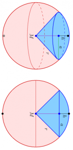
Attachment 2 shows the radiation from a point source in a corner. The surface area of the radiating wavefront will be 0.5 x Pi m^2 when r, the distance from the source, is 1 metre.
When the included angle at the apex of the spherical sector shown in Attachments 3 and 4 is 83 degrees (to the nearest whole number) then the area of the spherical cap at a radius of 1 metre will also be 0.5 x Pi m^2.
Would this be a way of anticipating a ‘sum’ of folding increments if using 90/180/270/360 as phase per a sine wave vs frequency in the folding a tapped horn?
I can't see how 🙂.
Attachments


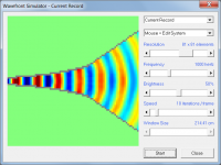
Thanks for the spherical radiation representation. I've been waiting for something like this for a long time. Is the change going to reflect in the waveform simulator as well?
Is the change going to reflect in the waveform simulator as well?
No, the Wavefront Simulator does not take the solid radiation angle into account.
I guess the appropriate boundaries could always be added manually by the user if required, as shown in the attachment.
Attachments
Ok, two more suggestions for future features... 🙂
1. Include Ang as an option in the Bandpass Wizard. Right now it's only accessible from the Input Parameters screen.
2. Include an option to set Path for the BP6P model, to represent the shortest distance between the vent for the front chamber and the vent for the rear chamber. I suspect the power response will change at upper frequencies as this distance is changed.
- Home
- Loudspeakers
- Subwoofers
- Hornresp