 waveguides for tweeters ?
logarithmic sliders
Hi
please can the value sliders in Hornresp be made logarithmic? For example in the filter tool trying to select a large value C in series with a loudspeaker requires pulling the slider to the right hand side dozens of times.
cheers
Phil
Hi
please can the value sliders in Hornresp be made logarithmic? For example in the filter tool trying to select a large value C in series with a loudspeaker requires pulling the slider to the right hand side dozens of times.
cheers
Phil
pressing shift plus clicking at the very end of the slider bar moves it by a large increment.
For example in the filter tool trying to select a large value C in series with a loudspeaker requires pulling the slider to the right hand side dozens of times.
Hi Phil,
As Mark and Sabbelbacke have indicated, there are other less labour-intensive ways to go about it 🙂.
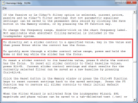
See the highlighted Help file instructions below for details.
(I haven't tried it, but I suspect that having logarithmic scales on the sliders would actually make them quite difficult to use).
Kind regards,
David
Attachments
A QUESTION ABOUT HORNS
Hello,
i want to ask a question, i have a bass horn designed.
The horn only has conical the sides, papalell to ground is horizontal.
In this case S1 wont be the hole in front of the driver and would be the width of the hole in all the height of the mouth, is this true?
in pdf i sent you can view 2 solutions, one has much more work.
i need the upper surface plain in order to move my midhorns. Or do a bigger chamber to position and even rotate (aim) the oris horns
i can send the plans and hornresp file in case someone wants to help
thanks
Attachments
Last edited:
Hi RLRB,
Simulate your first (top) design as shown the first attachment (not to scale).
Simulate your second (bottom) design as shown in the second attachment (not to scale).
Kind regards,
David
The horn only has conical the sides, papalell to ground is horizontal. In this case S1 wont be the hole in front of the driver and would be the width of the hole in all the height of the mouth, is this true?
Simulate your first (top) design as shown the first attachment (not to scale).
in pdf i sent you can view 2 solutions, one has much more work.
Simulate your second (bottom) design as shown in the second attachment (not to scale).
Kind regards,
David
Attachments
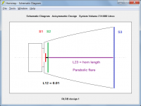

Simulate your first (top) design as shown the first attachment (not to scale).
Just to clarify, S2 = width of S1 throat area * height of S3 mouth area
Hi RLRB,
Simulate your first (top) design as shown the first attachment (not to scale).
Simulate your second (bottom) design as shown in the second attachment (not to scale).
Kind regards,
David
That's EXACTLY how I model all my BP4'S and BP6's.
Attachments
Last edited:
Hi, this new QL quality factor setting has really thrown a spanner in the works of my understanding of hornresp, could someone help me understand what it is in very simple terms and what determines what the value should be?
It knocks off 5db from my port output on most of my ported designs when using the default value, completly screwing the response curve I was aiming for
What really confuses me is that it doesn't seems to apply when making a ported box using vtc/atc for the box and s1/s2 for the port, or in any of the bandpass options? it seems like this should be greatly affecting an 8th order if it affects a ported box so drastically
From what I understand it should be a more accurate representation of the real world output, but why does it only apply to a ported enclosure built a certain way in the program and not anything else? should I even be worrying about this setting so much?
Sorry if this question is all over the place and poorly written compared to others on here
could someone help me understand what it is in very simple terms and what determines what the value should be?
Post #10991 linked below may help:
https://www.diyaudio.com/forums/subwoofers/119854-hornresp-1100.html#post6308267
I am hoping if someone can explain how to use the Loudspeaker Wizard / Power / Filling Fr1 and Tal1 values? What should these be to set a typical material at various densities?
It was suggested (by someone, somewhere - but I'll be darned if I can find it again!) to set the Fr1 to '1' to simulate the real world flex of the cabinet panels? The modeler (apparently) has "perfectly stiff" panels, which causes more extreme spikes and dips; was the thinking behind this, I think.
It was suggested (by someone, somewhere - but I'll be darned if I can find it again!) to set the Fr1 to '1' to simulate the real world flex of the cabinet panels? The modeler (apparently) has "perfectly stiff" panels, which causes more extreme spikes and dips; was the thinking behind this, I think.
What should these be to set a typical material at various densities?
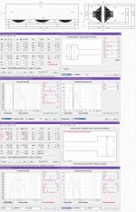
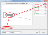
Ideally you really need to know the actual airflow resistivity value for the particular absorbent filling material that you intend using. If the chosen resistivity value is less than 1000 mks rayls/m and the Schematic and Filling options are selected, then the equivalent amount of Polyfill required to achieve the specified Fr1 and Tal1 settings will be shown in kilograms. This can sometimes be a useful indicator to check that you are "in the ballpark" when you are not too sure what value of Fr1 to use. The Tal1 value effectively specifies the volume of the filling material, and its position in the loudspeaker system.
Many Hornresp users simply adjust the Fr1 and Tal1 values to get an indication of how the response will be affected, and then just add material to the finished loudspeaker in the position they have specified, until they are happy with the overall result. Not a very scientific approach, but it seems to work quite well. The best way of course, as indicated at the very beginning, is to know the airflow resistivity value of the absorbent filling material that you intend using.
Attachments
What really confuses me is that it doesn't seems to apply when making a ported box using vtc/atc for the box and s1/s2 for the port
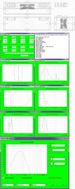
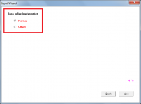
That's because Hornresp has no way of knowing that the specified design is intended to be operated as a bass reflex loudspeaker. For this reason also, no end correction will be added to the first (port tube) segment. If you want to specify a bass reflex speaker, either normal or offset, then the correct way to do it is as generated by the Input Wizard.
Attachments
Ideally you really need to know the actual airflow resistivity value for the particular absorbent filling material that you intend using. If the chosen resistivity value is less than 1000 mks rayls/m and the Schematic and Filling options are selected, then the equivalent amount of Polyfill required to achieve the specified Fr1 and Tal1 settings will be shown in kilograms. This can sometimes be a useful indicator to check that you are "in the ballpark" when you are not too sure what value of Fr1 to use. The Tal1 value effectively specifies the volume of the filling material, and its position in the loudspeaker system.
Many Hornresp users simply adjust the Fr1 and Tal1 values to get an indication of how the response will be affected, and then just add material to the finished loudspeaker in the position they have specified, until they are happy with the overall result. Not a very scientific approach, but it seems to work quite well. The best way of course, as indicated at the very beginning, is to know the airflow resistivity value of the absorbent filling material that you intend using.
Thanks David - I didn't realize the weight of polyfill was displayed when you add a value. D'oh! And 700 in your example is much higher than what I had been experimenting with - if 700 is just 0.069 kg, then a value of 15 or 20 could not be achieved. And that was all it took to knock the spikes down by over half.
So I think I will make adjustments to get a rising knee at the ~40Hz end of the response, to compensate for the fill flattening it back out.
You have given me an idea of what is reasonable and I can go from there - thank you!
- Home
- Loudspeakers
- Subwoofers
- Hornresp