Hi Sam:
I'm curious about what you are trying to do. When I consider multiple horns, I worry about lobing and comb filtering compromising the high frequency response, not extending it. To get get more bass from a single horn, consider making it a multiple entry horn per Danley's unity or synergy.
In any case, even if HR could simulate one driver connected to multiple horns, it wouldn't tell you anything about how those multiple horns summed together at the listening position, which I think would be the critical issue. The closest it comes to doing something like that is where it allows you to specify a path length difference between a horn or direct radiator output and a box vent. Even then, except for limited cases such as direct radiator and single segment horn, it tells you the sound power, not the SPL at a point in space.
Hi Cubana,
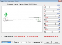
The tapped horn model you are using looks fine to me. To gain a bit more flexibility in specifying the expansion profile near the horn mouth you could perhaps use four segments rather than three, with the second tap point at S4, but that is about the only change I would consider making.
Thanks for the help, David! Indeed, the advantage of S4, and that's what happened.

Hi Cubana,
EDIT - The throat chamber seems a bit short when compared against your drawing. If Vtc = 20000 and Atc = 1000 then the length of the chamber is only 20 cm when the horn segment alongside is 228 cm. Did you mean Vtc to be 200000 perhaps?
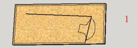
This is a very rough drawing:

This is a very rough drawing:
An externally hosted image should be here but it was not working when we last tested it.
My throat chamber comment was in relation to the original drawing 🙂.
Attachments
I understand, sorry 😉 😎 Thanks again for the help!My throat chamber comment was in relation to the original drawing 🙂.

Last edited:
This is a very rough drawing:
Hi Cubana,
Just a thought - your drawing shows the throat chamber exiting directly into the throat of the horn, rather than being offset some distance along the horn. For that reason should L12 (the axial distance between S1 and S2) perhaps be reduced to the minimum 0.01 cm in your simulation model?
Kind regards,
David


How to draw a chamber 20 liters in hornresp?🙄
Hi Cubana,
The cylindrical throat chamber is assumed to be oriented at right angles to the axis of the "unfolded" tapped horn, and is shown in the schematic diagram (plan view) as a dashed-line black circle at the throat-end of the horn, with the same centre point as the driver.
(If Atc = Sd the diameter of the driver diaphragm and the chamber will be identical, completely hiding the chamber beneath the dashed-line red circle representing the throat-facing side of the driver).
Kind regards,
David
Attachments
Hornresp Update 4030-170222
Hi Everyone,
BUG FIX
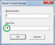
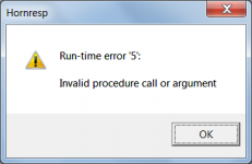
A number of other locations were found where it was possible to copy and paste negative values as inputs, generating fatal errors. See typical example in Attachments 1 and 2. Hopefully all the bugs of this type have now been cleared.
CHANGE 1
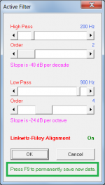
Main Active Filter settings are now permanently saved by pressing the F9 function key at the point of entry of the data, rather than the settings being saved later as part of the overall record saving process.
(Previously it was possible to permanently save intended temporary changes to the Main Active Filter settings without realising that the settings had been saved. Saving the filter settings now requires a deliberate action on the part of the user). See Attachment 3.
CHANGE 2
Slope and alignment settings are now also included when filter baselines are reset, and when filter settings are temporarily stored and recalled.
Kind regards,
David
Hi Everyone,
BUG FIX
A number of other locations were found where it was possible to copy and paste negative values as inputs, generating fatal errors. See typical example in Attachments 1 and 2. Hopefully all the bugs of this type have now been cleared.
CHANGE 1
Main Active Filter settings are now permanently saved by pressing the F9 function key at the point of entry of the data, rather than the settings being saved later as part of the overall record saving process.
(Previously it was possible to permanently save intended temporary changes to the Main Active Filter settings without realising that the settings had been saved. Saving the filter settings now requires a deliberate action on the part of the user). See Attachment 3.
CHANGE 2
Slope and alignment settings are now also included when filter baselines are reset, and when filter settings are temporarily stored and recalled.
Kind regards,
David
Attachments

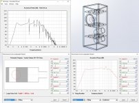
Hi David! Do I understand correctly? 🙂
An externally hosted image should be here but it was not working when we last tested it.
Or wrong? 😉
Hi Cubana,
Your understanding is near enough 🙂.
* The throat chamber is actually located as described in my earlier post.
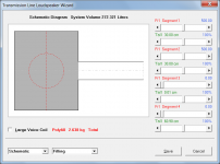
* The total "system volume" of 137.915 litres includes the throat chamber volume, as you have shown.
Segment 1 = 0.028
Segment 2 = 96.366
Segment 3 = 9.905
Segment 4 = 11.616
Vtc = 20.000
System = 137.915 litres
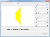
* The value specified for throat chamber volume Vtc should also include the effective air volume between the driver diaphragm and the front plane of the driver. The volume (indicated in yellow in the attachment) can be calculated using the Driver Front Volume tool.
* The overall horn length specified in Hornresp is 260 cm, not the 266 cm marked in red on the schematic diagram.
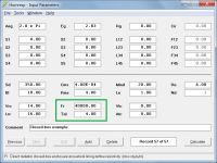
L12 = 0.10
L23 = 228.90
L34 = 15.50
L45 = 15.50
L15 = 260.00 cm
* Strictly speaking the flare expansion rate should be specified as Par rather than Con. It won't make any noticeable difference to the results either way, though.
Kind regards,
David
Attachments
Absolute beginner, rookie question, sorry...searched to no avail......
first DIY project, ported 18" sub, where I haven't used others' posted plans.
Finally time to learn...
Direct radiator, ported box: I use inputs Ap and Lpt for port area and length.
How do I get to inputs for fill material?
Thx, mark
first DIY project, ported 18" sub, where I haven't used others' posted plans.
Finally time to learn...
Direct radiator, ported box: I use inputs Ap and Lpt for port area and length.
How do I get to inputs for fill material?
Thx, mark
Absolute beginner, rookie question, sorry...searched to no avail......
first DIY project, ported 18" sub, where I haven't used others' posted plans.
Finally time to learn...
Direct radiator, ported box: I use inputs Ap and Lpt for port area and length.
How do I get to inputs for fill material?
Thx, mark
Vrc = box volume
Lrc = box depth
S1 = port height x width
S2 = port height x width
L12 = port length
Then you can use the lining fields.
Hmm, this puts the vent in front of the driver...........
You have to use L12, L23, offset [OD] driver, etc., to construct it. Copy the text file to HR's IMPORT folder to open, view, save, modify. Unfortunately you can't locate the vent on the baffle, so the sim in some cases won't be as accurate if you use this program that allows the driver, vent to be accurately located on the cab: Transmission Line
GM
Attachments
Absolute beginner, rookie question, sorry...searched to no avail......
first DIY project, ported 18" sub, where I haven't used others' posted plans.
Finally time to learn...
Direct radiator, ported box: I use inputs Ap and Lpt for port area and length.
How do I get to inputs for fill material?
Thx, mark
Hi Mark,
Do as GM suggests - using the Loudspeaker Wizard tool to modify his given design.
(With this example, absorbent filling material can only be added using the Loudspeaker Wizard).
Kind regards,
David
Attachments
Is there any other kind?
Hi GM,
I was thinking of the closed rear chamber situation, where Fr and Tal can be used to directly specify absorbent filling material from the main Input Parameters window, without the need to access the Loudspeaker Wizard tool.
Kind regards,
David
Attachments

A sim of a reflex cabinet modelled as an offset driver horn with no chamber certainly seems to work. It involves a bit more math to get the volume of the box correct.
This has really helped me as I have been struggling to make sense of a large reflex cabinet for a Tannoy 15" Monitor Gold. I had been concerned about the rise in response at the port frequency, but now I can see how stuffing the cabinet will help tune the response.
On the subject of stuffing I am struggling with how to set the mks rayls/m figure.
How could I find out this parameter for different acoustic adsorbent materials?
I see that Hornresp can estimate the amount of polyfill required. But I have no clues how to set the parameter for different materials.
Regards Martin (Xoc1)
Attachments
Thank you all, gentlemen.
GM, David, I'll go to work with the txt file (big thx!) as instructed.
GM, David, I'll go to work with the txt file (big thx!) as instructed.
Hi GM,
I was thinking of the closed rear chamber situation, where Fr and Tal can be used to directly specify absorbent filling material from the main Input Parameters window, without the need to access the Loudspeaker Wizard tool.
Kind regards,
David
Ah! Thanks! Totally forgot as I never use it since I couldn't figure out how to correlate it to my favored acoustic fiberglass insulation without a lot of testing.
GM
Hmm, this puts the vent in front of the driver...........[/url][/B]
GM
You are absolutely right. I was also thinking
Vrc = 0.
Lrc = 0.
S1 = box height x box width.
S2 = box height x box width.
L12 = box depth.
S3 = box height x box width.
L23 = 0.01
S4 = port height x port width.
L34 = port length.
Of course, I did both responses from my cellphone.
I'm trying to visualize the HR input screen from memory.
We need a mobile version of HR!
- Home
- Loudspeakers
- Subwoofers
- Hornresp