Hi just a guy,
Why not just change the value of Mmd in Hornresp, and if you want to know the resultant Thiele-Small equivalent parameter values, double-click on the Sd input box?
Kind regards,
David
Yes, ok, for some reason I didn't follow all the parameter relationships all the way back.
Just changing Mmd does indeed affect all the parameters that the formulas I showed affect.
So essentially you just need to change Mmd and that will cover all changes made to all t/s from changing the moving mass. So it's a lot easier than I thought, which makes me wonder why you thought this wasn't going to be possible, since it's already more than possible, this feature is already there.
Hi just a guy,
In the book 'Introduction to Electroacoustics and Audio Amplifier Design' Marshall Leach gives simulation models for closed-box and vented-box loudspeaker systems, based on the work by Thiele and Small.
Kind regards,
David
I'm not familiar with the book or it's contents, all I know is that you mentioned the already existing "System Design - With Driver" tool, which I don't think is going to be very useful for this purpose unless the system you are designing is a full size flh.
So it's a lot easier than I thought, which makes me wonder why you thought this wasn't going to be possible, since it's already more than possible, this feature is already there.
Hi just a guy,
In his original post, papasteack said:
"we should move driver parameters while staying "realistic", so that moving one parameter moves the others, helping so aiming for a driver parameter set,"
I interpreted this as wanting to be able to change Mmd for example, and to have Sd, Bl, Cms, Rms, Le and Re automatically adjust to maintain an overall "realistic" set of parameters. I am not aware of a process that would allow this to be done.
What Hornresp enables us to do is to change the values of driver electro-mechanical parameters and to have the relevant equivalent Thiele-Small parameters automatically updated accordingly, using the standard conversion formulas. This is different to what was being requested, as I understand it.
Kind regards,
David
a question on particle velocity; how is it calculated for a direct radiator? it seems to be a function of excursion (or frequency) & Sd
@papasteack
Regarding the issue "changing some Parameters - others change automatically": You have to keep in mind, that most of the TSP are calculated from others. But not all of them have a direkt relationship to the physical parameters of the driver, they are mathematical constructs with no "real live" equivalent and they are derived from a bunch of other parameters..
So you don´t enter "weight of the magnet" or "weight of the cone".. in a typical Speaker simulation software. You enter measured specs which come from different measurement methods (added mass, Laser, Volume change of measurement enclosure) etc...
So most of the TSP depend on a combination of the physikal attributes of the driver. This means, calculating them only works "one way". For example: The resonance frequency depends on the weight of the cone, including the attached Voicevoilformer, the windings, the compliance of the spider, the surrounding, the size of the cone, etc... If you would want to try a speaker with a higher resonance frequency, you can´t simply change this value - no software on earth can guess which physical parameters are changed know. Did you harden the suspension? did you make the cone lighter? Changed the Material of the voicecoil? Or another cone-material?
The most basic TSP are already the ones which are entered into hornresp when you add a new driver. These calculate all other Parameters (Qts depends on Qms and Qes, so Qes and Qms are entered, etc..)... So in a limited way, there is a way of changing some parameters and having the other (dependend ones) stay "realistic"..
I think I understand what you are trying to do. You would like to see if a different driver would work in a given cabinet if you change some specs of the driver. One could think of this as the way some R&D departments work - They "pick" the single parts of a speaker and see what happens - building a hornsubwoofer - I need a more rugged cone. Having the need for a Subbwooferdriver in a ported box - more xmas is required, so we need a longer voicecoil or a longer gap plus a longer coil, so we just order it at the "custom speaker shop" 🙂
Most of the times, it works different... You can´t simply change some specs and have a nice speaker in every case... They all influence each other - so it´s a job of a good speaker designer to keep everything in balance. Simply changing the voicecoil of a good sounding midbass with a longer one to make a subwoofer often results in a bad product. The cone has to be more rugged, the spiders/Suspension part hast to be changed for more excursion capability, the magnetc flux is not enough, so a motor change is need, etc... and with every "partsswapping" many parameters change... In some cases small changes are ok, but only to a certain degree.
Of course, if your R&D department is so advanced, that you really can deal with all these changes, you do things that way. JBL has all the ressources they need to develop transducers exactly for a wanted application, a targeted price, weight etc... in their own facilities...
But the majority of speaker builders take whats offered on the market and build their boxes around this. Some have custom drivers which are not available for free, these are the ones with the "small changes from the stock model" mentioned above.
If you want to take a closer look on how the physical specs of a transducer are related to the TSP we use to simulate, take at the software of loudsoft
FINE Speaker Test and Design - Loudsoft Denmark
I think Geedles "speak" had some interesting simulation capabilities here, too, it´s free now:
Speak downloads
Or load WinISD and play around - it calculates depending parameters from other ones.
But whatever you do - you need to know what you do. Simply turning some knobs to get a nice looking curve on the screen doesn´t make a well designed Speaker. And the more you understand of the topic, the more self explaning are the limitations of your request.
So to sum it up: What you wanted in full extend is not possible here. But you can deal with the matter with the driver input data in hornresp and with the software mentioned above to get a felling. Take a look at equiations how parameters are derived. TSPcheck is a nice program for this purpose, too.
a question on particle velocity; how is it calculated for a direct radiator? it seems to be a function of excursion (or frequency) & Sd
Hi 3ll3d00d,
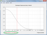
Particle velocity at the surface of a direct radiator diaphragm is a function of diaphragm displacement (excursion) and frequency.
Sd only becomes involved if you wish to calculate volume velocity (volume velocity = particle velocity * Sd).
If:
Dd = diaphragm displacement
f = frequency
Then:
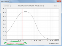
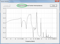
Particle velocity = Dd * 2 * Pi * f
To give a numerical example, in Attachment 1 the peak diaphragm displacement is 2.2581 mm or 0.0022581 metres at 100 Hz. The peak particle velocity is 0.0022581 * 2 * Pi * 100 or 1.4188 m/sec, as shown in Attachment 2.
Kind regards,
David
Attachments
thanks for the explanation. My memory/knowledge of this sort of thing is extremely rough but is that simply angular velocity * displacement?Particle velocity at the surface of a direct radiator diaphragm is a function of diaphragm displacement (excursion) and frequency.
is that simply angular velocity * displacement?
Either angular velocity * displacement or angular frequency * displacement.
(Angular frequency is the magnitude of the vector quantity angular velocity).
This might be an odd/daft question but is this calculating the same physical quantity as produced on the port outlet/particle velocity graph? I thought that was more like airflow speed. Google hasn't helped me much here as terminology seems inconsistent in the web (or I am looking for the wrong things which is quite possible).Either angular velocity * displacement or angular frequency * displacement.
(Angular frequency is the magnitude of the vector quantity angular velocity).
is this calculating the same physical quantity as produced on the port outlet/particle velocity graph? I thought that was more like airflow speed.
Hi 3ll3d00d,
It is the same physical quantity.
The air particles vibrate back and forth, there is no net airflow. The driver would need to be replaced by an electric fan to have an airflow 🙂.
The peak particle velocity is the velocity of the air particle as it passes through the point of zero displacement. The particle velocity is zero at the points of maximum displacement.
Kind regards,
David
thanks for clarifying.Hi 3ll3d00d,
It is the same physical quantity.
The air particles vibrate back and forth, there is no net airflow. The driver would need to be replaced by an electric fan to have an airflow 🙂.
The peak particle velocity is the velocity of the air particle as it passes through the point of zero displacement. The particle velocity is zero at the points of maximum displacement.
Kind regards,
David
fwiw I mentioned airflow because of the way it is described in this paper - http://koti.kapsi.fi/jahonen/Audio/Papers/AES_PortPaper.pdf - and particularly the use of an anemometer to measure velocity (which I thought was a device for measuring air speed).
Last edited:
I mentioned airflow because of the way it is described in this paper - http://koti.kapsi.fi/jahonen/Audio/Papers/AES_PortPaper.pdf - and particularly the use of an anemometer to measure velocity (which I thought was a device for measuring air speed).
A hot-wire anemometer was used to measure the instantaneous velocity of the oscillating air particles. A hot-wire anemometer is quite different to the instrument used by a weather station to measure wind speed 🙂. The air in the port is reacting to the vibration of the driver diaphragm. The air only moves back and forth, there is no net airflow out of the port.
Hornresp Update 3990-161101
Hi Everyone,
CHANGE 1
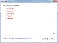
An Input Wizard tool has been added to hopefully make it easier for new users to get started in Hornresp. The tool is located under the Help menu, and can be accessed when the Input Parameters window is visible.
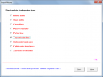
The tool enables a user to configure a loudspeaker system by selecting options from a series of option lists. Hornresp then automatically generates a representative example design of the specified system, which the user can modify as desired. The only system type that cannot be specified using the tool is the multiple entry horn loudspeaker.
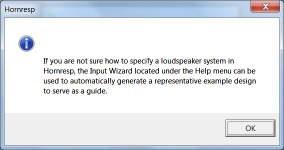
A message advising the user of the Input Wizard tool is displayed the first time that Hornresp is run after the initial installation of the program.
Attachment 1 shows the initial advisory message.
Attachment 2 shows the primary direct radiator loudspeaker option list.
Attachment 3 shows the primary horn loaded loudspeaker option list.
CHANGE 2
The Sound Pressure and Particle Velocity menu choice descriptions have been made more specific, and additional related explanatory information has been included in the Help file.
Attachment 4 shows one of the new menu descriptions.
Attachment 5 shows the associated chart.
See the post linked below for further background information on why the change was made.
http://www.diyaudio.com/forums/subw...bass-horn-design-question-30.html#post4868614
CHANGE 3
ME1, ME2 and passive radiator loudspeaker schematic diagrams can now be printed out as hard copies.
Kind regards,
David
Hi Everyone,
CHANGE 1
An Input Wizard tool has been added to hopefully make it easier for new users to get started in Hornresp. The tool is located under the Help menu, and can be accessed when the Input Parameters window is visible.
The tool enables a user to configure a loudspeaker system by selecting options from a series of option lists. Hornresp then automatically generates a representative example design of the specified system, which the user can modify as desired. The only system type that cannot be specified using the tool is the multiple entry horn loudspeaker.
A message advising the user of the Input Wizard tool is displayed the first time that Hornresp is run after the initial installation of the program.
Attachment 1 shows the initial advisory message.
Attachment 2 shows the primary direct radiator loudspeaker option list.
Attachment 3 shows the primary horn loaded loudspeaker option list.
CHANGE 2
The Sound Pressure and Particle Velocity menu choice descriptions have been made more specific, and additional related explanatory information has been included in the Help file.
Attachment 4 shows one of the new menu descriptions.
Attachment 5 shows the associated chart.
See the post linked below for further background information on why the change was made.
http://www.diyaudio.com/forums/subw...bass-horn-design-question-30.html#post4868614
CHANGE 3
ME1, ME2 and passive radiator loudspeaker schematic diagrams can now be printed out as hard copies.
Kind regards,
David
Attachments

WOW !
@ David McBean
Dear David, the new addition of a Help Wizard with default starter projects for ALL those possible designs, is something i requested, i think a couple of years ago. At the time i'm sure you gave your Infamous reply INGTH ! Well i can't Thank you enough for taking the time & figuring out how to include it at last 🙂 This is bound to be a Big help to a lot of people, including me 🙂
If you could possibly find a way to enable at least 2 visable windows to be viewed at once in real time, for eg Schematic & Power, that would make designing so much easier/quicker. As it is, altering things in one can seem ok, only to find swiching back to the other/s it isn't ! The amount of switching/altering between windows can become very tedious & frustrating, at least i've found it so.
Once again, THANX for all you've done, & continue to do for us. It's VERY much appreciated 🙂
Hi Zero D,
You certainly made some suggestions recently to 'just a guy' regarding possible tutorial ideas, but I don't recall an earlier request to add a "Help Wizard" feature to Hornresp. I would be very interested to see the post if you did, just to make sure that I haven't missed anything.
http://www.diyaudio.com/forums/subwoofers/119854-hornresp-659.html#post4817478
As previously indicated, the way that Hornresp has evolved, multiple open windows is simply not an option.
You refer to altering things and switching, so I assume that you may be using the Loudspeaker Wizard. If so, remember that the schematic diagram can be instantly checked from any other window by pressing and holding down the S key. Releasing the S key instantly reverts back to the original window.
As far as the main windows are concerned, pressing the F2 function key moves to the next window, and pressing Shift+F2 moves to the previous window. Pressing the Esc key from any chart window returns to the input parameters window.
Kind regards,
David
the new addition of a Help Wizard with default starter projects for ALL those possible designs, is something i requested, i think a couple of years ago.
You certainly made some suggestions recently to 'just a guy' regarding possible tutorial ideas, but I don't recall an earlier request to add a "Help Wizard" feature to Hornresp. I would be very interested to see the post if you did, just to make sure that I haven't missed anything.
http://www.diyaudio.com/forums/subwoofers/119854-hornresp-659.html#post4817478
If you could possibly find a way to enable at least 2 visable windows to be viewed at once in real time, for eg Schematic & Power, that would make designing so much easier/quicker. As it is, altering things in one can seem ok, only to find swiching back to the other/s it isn't ! The amount of switching/altering between windows can become very tedious & frustrating, at least i've found it so.
As previously indicated, the way that Hornresp has evolved, multiple open windows is simply not an option.
You refer to altering things and switching, so I assume that you may be using the Loudspeaker Wizard. If so, remember that the schematic diagram can be instantly checked from any other window by pressing and holding down the S key. Releasing the S key instantly reverts back to the original window.
As far as the main windows are concerned, pressing the F2 function key moves to the next window, and pressing Shift+F2 moves to the previous window. Pressing the Esc key from any chart window returns to the input parameters window.
Kind regards,
David
@ David McBean
Re - request to add a "Help Wizard" feature to Hornresp
I wouldn't have called it that. I recall requesting something similar to suggestions i recently made to 'just a guy'. I'll see if i can locate my post.
OK, pity though, & no harm in asking 😉
Thanx for the F2 etc tips 🙂
Re - request to add a "Help Wizard" feature to Hornresp
I wouldn't have called it that. I recall requesting something similar to suggestions i recently made to 'just a guy'. I'll see if i can locate my post.
multiple open windows is simply not an option.
OK, pity though, & no harm in asking 😉
Thanx for the F2 etc tips 🙂
Possible bug?
Hi David,
Post #6817: "... the schematic diagram can be instantly checked from any other window by pressing and holding down the S key. Releasing the S key instantly reverts back..."
Using Hornrresp Product Number 3990-161101 in Windows 10:
s or S does not do anything as far as going from any window to the schematic windows (checked also the Ctrl/Alt/Fn w/ s key combinations). Esc return to Input works. F2 to cycle through the windows works too. Tried different simultions.
Thanks for the continuing effort.
Regards,
- Home
- Loudspeakers
- Subwoofers
- Hornresp