Thank you, but that is rather not what I had in mind.

Maybe the stubs but with two descriptions (so it can be a chamber/vent shape) like OD1 allows?
is there a chance that in the future it will be possible to simulate damping with either polyurethane foam or BASF Basotect melamine foam?
If the foam completely fills the specified length Tal1 of the segment and the flow resistivity Fr1 is known, then it can be done now. No further development work is planned for the absorbent filling material model used in Hornresp.
is the possibility of Hornresp to simulate an additional tunnel branch that can serve as a quarter-wave attenuator?
It cannot be done if the driver is offset.
Can't the "Offset-Driver / Offset-Vent" sim accomplish the same thing? Basically, the section after the vent can double as the "tunnel branch"
Can't the "Offset-Driver / Offset-Vent" sim accomplish the same thing?
Thanks Brian, it should certainly go very close. Why didn't I think of that? 🙂
Hey DMB, can we see the HR Input screen to that Closed Mouth Horn?
I like that Schematic Diagram!
Bandpass 4 Life 🧊🔊📣🎼
I like that Schematic Diagram!
Bandpass 4 Life 🧊🔊📣🎼
Attachments
Hornresp Update 5720-250205
Hi Everyone,
CHANGE 1
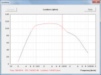
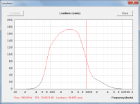
A chart has been added that displays the loudness or perceived sound intensity of the power response sound pressure between 20 Hz and 10000 Hz, with the results being calculated in either phon (logarithmic) or sone (linear) units using the normal equal-loudness-level contours given in ISO 226:2023.
Results are valid from a lower limit of 20 phon to:
An upper limit of 90 phon from 20 Hz to 4000 Hz.
An upper limit of 80 phon from 5000 Hz to 12500 Hz.
Phon and sone values outside the limits are shown in red and are informative only, because of the lack of supporting experimental data.
The chart is selected from the acoustical power chart window using the Tools > Loudness menu commands. It is not applicable to the loudspeaker wizard.
Attachments 1 and 2 show the results for the default record (with resonances masked). Note how the SPL and phon values are the same at 1000 Hz.
CHANGE 2
Double-clicking with the Ctrl key pressed on a schematic diagram that has the driver or passive radiator diaphragm shown as a straight line, now increases the width of the line to make it easier to see. Double-clicking again with the Ctrl key pressed resets the diaphragm line back to the default thickness. Not applicable to band pass enclosure systems as they have thicker lines as standard.
Attachment 3 refers.
CHANGE 3
Acoustic centres displayed on the loudspeaker wizard schematic diagram are now hidden by double-clicking, rather than by pressing the Esc key.
BUG FIX 1
A fatal error was generated if a blank was entered into the Vrc or Lrc field of a Nd record with a passive radiator specified. This has now been fixed.
BUG FIX 2
If a ME1 and/or ME 2 record was activated it was possible to select the default Nd record and then open the Multiple Entry Horn Wizard. A fatal error was generated when the wizard was closed. This bug has now been fixed - the default record can no longer be used with the MEH wizard.
BUG FIX 3
A fatal error was generated if:
1. The Hornresp Help file was opened.
2. The Find tool opened using either the File > Find menu commands or the Ctrl+F shortcut.
3. The Find tool subsequently closed.
4. The Ctrl+F keys then pressed in an attempt to re-open the Find tool.
This bug has now been fixed.
Kind regards,
David
Hi Everyone,
CHANGE 1
A chart has been added that displays the loudness or perceived sound intensity of the power response sound pressure between 20 Hz and 10000 Hz, with the results being calculated in either phon (logarithmic) or sone (linear) units using the normal equal-loudness-level contours given in ISO 226:2023.
Results are valid from a lower limit of 20 phon to:
An upper limit of 90 phon from 20 Hz to 4000 Hz.
An upper limit of 80 phon from 5000 Hz to 12500 Hz.
Phon and sone values outside the limits are shown in red and are informative only, because of the lack of supporting experimental data.
The chart is selected from the acoustical power chart window using the Tools > Loudness menu commands. It is not applicable to the loudspeaker wizard.
Attachments 1 and 2 show the results for the default record (with resonances masked). Note how the SPL and phon values are the same at 1000 Hz.
CHANGE 2
Double-clicking with the Ctrl key pressed on a schematic diagram that has the driver or passive radiator diaphragm shown as a straight line, now increases the width of the line to make it easier to see. Double-clicking again with the Ctrl key pressed resets the diaphragm line back to the default thickness. Not applicable to band pass enclosure systems as they have thicker lines as standard.
Attachment 3 refers.
CHANGE 3
Acoustic centres displayed on the loudspeaker wizard schematic diagram are now hidden by double-clicking, rather than by pressing the Esc key.
BUG FIX 1
A fatal error was generated if a blank was entered into the Vrc or Lrc field of a Nd record with a passive radiator specified. This has now been fixed.
BUG FIX 2
If a ME1 and/or ME 2 record was activated it was possible to select the default Nd record and then open the Multiple Entry Horn Wizard. A fatal error was generated when the wizard was closed. This bug has now been fixed - the default record can no longer be used with the MEH wizard.
BUG FIX 3
A fatal error was generated if:
1. The Hornresp Help file was opened.
2. The Find tool opened using either the File > Find menu commands or the Ctrl+F shortcut.
3. The Find tool subsequently closed.
4. The Ctrl+F keys then pressed in an attempt to re-open the Find tool.
This bug has now been fixed.
Kind regards,
David
Attachments
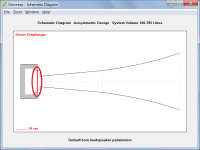
Wow, so the Input Parameters looks like a negative flare horn (S1-S4) even though the Schematic Diagram comes out a positive flare horn.
I see its a left to right situation.
I really dig how that Schematic Diagram came out!
I'm on my work laptop so I can't play with latest version. Does the OP (Offset Vent?) part of ODOP equal the NOTE: Lossless message?
No. FWIW, I just put in all in by hand and it came up QL = 7. As you probably already know, just go into the LS Wizard and change the QL to what you want (under Chamber). I even toggled Fta / Clo a couple times and it stayed lossy--but I'm working in the latest rev.
Wow, so the Input Parameters looks like a negative flare horn (S1-S4) even though the Schematic Diagram comes out a positive flare horn.
The schematic diagram shows a negative flare also (the closed-throat is at the left-hand end and the closed-mouth at the right-hand end).
Does the OP (Offset Vent?) part of ODOP equal the NOTE: Lossless message?
As indicated in Post #15,483 Hornresp does not have a model specifically intended for the system described in Post #15,478. The model suggested by Brian in Post #15,484 is about the best that is available. Using this compromise model Hornresp assumes that the loudspeaker is a bass reflex design with offset driver and offset port. It also assumes a default QL vented-box system losses value of 7 and that the port tube has an end correction.
For the transmission line / stub system being simulated however, the QL value should be set to Lossless and the port tube end correction compensated for. The Lossless note is related to QL and is referring to the total bass reflex system, not just the port tube. In reality the TL design in question is not actually lossless because absorbent filling material has been specified.
As you probably already know, just go into the LS Wizard and change the QL to what you want (under Chamber).
Alternatively, just double-click on the Input Parameters window QL = 7 message in Edit Mode and set the slider to the desired value.
(Set to maximum for Lossless).
Perhaps my little tutorial will help somebody.
Well done on producing a very comprehensive document. I have read through the complete tutorial, making some observations as I went along. You may be interested in the following comments.
1. The specifications given for the Rival driver are not all Thiele-Small parameters. This is a common misunderstanding and even some driver manufacturers get it wrong. BL, Cms and Mms are mechanical parameters, not T-S parameters.
2. There is a typographical error - Continous Power should be Continuous Power
3. It is not necessary to press Edit before Calculate if no changes are required to be made before calculating the results. Only the Calculate button needs to be pressed in that case.
4. The Loudspeaker Wizard can only be opened from the Input Parameters window, but it is not necessary to press the Calculate button first. It is however necessary to have pressed the Edit button.
5. It is possible to specify box stuffing in a bass reflex type design, but not by using the standard bass reflex template.
6. Another typo - about 3-4 inchs should be about 3-4 inches.
7. A parabolic profile is the one to use if the transmission line duct has two parallel sides and two sloping sides (i.e. the cross-sectional area changes linearly along the axial length).
8. S1, S2, etc are cross-sectional areas, not segment numbers. S is the symbol traditionally used in audio to represent area (Sd is diaphragm area, for example).
9. L12 (pronounced "L one-two" not "L twelve") is the distance between the planes of S1 and S2, or the axial length of segment 1.
10. Should "Rule of Fum" be "Rule of Thumb"?
11. If the centre of the woofer is 100 cm from the floor and the centre of the port at the back is 18 cm from the floor, and the cabinet is 38 cm from front to back then from Pythagorus, the Path value will be ((100 - 18) ^ 2 + 38 ^ 2) ^ 0.5 = 90.38 cm. (The Path length is the straight line distance between the two point sources).
A chart has been added that displays the loudness or perceived sound intensity of the power response sound pressure between 20 Hz and 10000 Hz
A bug was inadvertently introduced when the above chart was added. All secondary charts are now limited to the 20 - 10000 Hz frequency range, not just the loudness chart. The driver input power chart is shown below as an example. The bug will be fixed in the next update.
Hornresp Update 5720-250210
Hi Everyone,
BUG FIX
The bug reported in the post above (#15,497) has now been fixed.
Kind regards,
David

Hi Everyone,
BUG FIX
The bug reported in the post above (#15,497) has now been fixed.
Kind regards,
David
Looking forward to this.@David McBean - thank you for your kind and patient feedback. New revision soon!
1. Could you please look into creating this as an online wiki (wikihow etc.)? Then David and some of the more experienced users can directly edit and update it.
2. There is still considerable confusion regarding which LS/horn/TL types are supported by HR and how to access them. On the Input parameters page, double clicking the Con label cycles it Con-Exp-Par-Con. Clicking the input field next to it and type H for hyperbolic horn, S for spherical, T for tractrix, .... I haven't gone through the entire alphabet yet, LOL, but I'm sure there are more such triggers. Each of these works differently, and spawns a different calculator when the input field is double clicked. Each of these needs an image and an explanation.
3. We need a table showing which features and tools and wizards are available for each horn type. E.g. if the first segment is spherical, subsequent segments are not available. Even the hypex approximator vanishes, leave alone the loudspeaker wizard.
4. I'm sure instructions of how to get back to the original view after applying a particular tool like Max SPL are there somewhere in the help file, but finding them is tough. Currently I run the tool again, with a blank in the relevant field.
1. Could you please look into creating this as an online wiki
The tutorial produced by joetekubi shows how to design a transmission line loudspeaker using Hornresp. It seems that what you are looking for is more generalised information on how to operate Hornresp and to use the features provided in the program. There is no better reference for that than the Hornresp Help file, and there is probably little to be gained in duplicating the information it contains in another document.
2. There is still considerable confusion regarding which LS/horn/TL types are supported by HR and how to access them.
See the Loudspeaker Models section of the Help file.
Generic templates for most of the models can be produced using the Input Wizard under the Help menu.
I haven't gone through the entire alphabet yet, LOL, but I'm sure there are more such triggers.
You are aware of the spherical flare, so simply type spherical or sph into the Help File > Find tool. The first reference the tool finds will tell you all that you need to know.
Similarly for the other points you raise - the Help File > Find tool is your friend.
Recommendations:
1. Take the time to read the Help file from beginning to end at least once. You will be surprised at what you will learn.
2. If you have a printer then print out a hard copy of the Help file and keep it as a handy reference. Mark up / highlight sections of specific interest.
- Home
- Loudspeakers
- Subwoofers
- Hornresp