Window Acoustical Power, Tools menu Particle velocityAny way to get this sim to show the particle velocity at the vent rather than at the driver?

I'm on my phone, but I think you can get separate vent and driver velocities with OD function models.
It's in the Tools menu, but at the top of the menu.
It's in the Tools menu, but at the top of the menu.
Any way to get this sim to show the particle velocity at the vent rather than at the driver?
No.
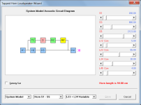
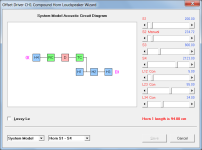
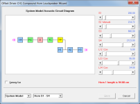
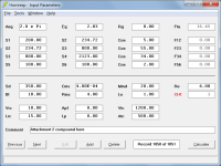
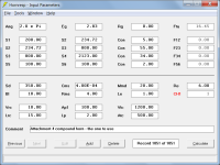
It is however possible to find exactly what you want by using an equivalent CH design with the 6.48 cm end correction added to segment 1, or to find almost exactly what you want by simply removing the 1 mm thick first segment which essentially does nothing, and set QL= Lossless in the resulting bass reflex design.
Inserted images 1 and 2 show the CH option, inserted images 3 and 4 show the bass reflex option.
(The results are effectively identical for the two options).
I
Hornresp Update 5630-241110
Hi Everyone,
CHANGE
A workaround has been put in place to prevent the second of the two Windows - Wine/Linux incompatibility problems reported in Post #15,305 from occurring.
BUG FIX 1
It is no longer possible for passive radiator parameter values to be set to zero. Posts #15,285 and #15,286 refer. My thanks to Roman for reporting the problem.
BUG FIX 2
The acoustical impedance at the port opening of a BP4 enclosure was not being updated correctly when the port area was changed using the Ripple and Gain features. This has now been fixed.
Kind regards,
David
Feature request - is it possible to have the displacement graph show the value at the point of maximum diaphragm displacement above Fb?
Similar to the example below:

Similar to the example below:
is it possible to have the displacement graph show the value at the point of maximum diaphragm displacement above Fb?
As you have shown by your example it is already possible to determine the value of maximum displacement reasonably accurately simply by direct observation. If a more precise value and the frequency at which it occurs is required then they can be found by sampling on the main window. Just click somewhere near the maximum and then use the left and right arrow keys to find the peak value, as illustrated in the second image below.
I would prefer not to complicate things further by adding the suggested feature. In other words, it's not going to happen 🙂.
Hello David,
Would you consider the possibility to create a new Hornresp model?
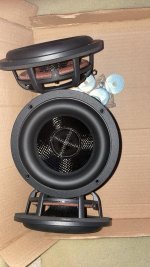
I saw the loudspeaker design people refers to as PM60 and PM90, as you can see from attachments #1 and #1. It makes me curious to check the SPL response but after having a CAD model and all inputs for hornresp I realized that with current models available it's not possible to simulate this design properly.
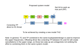
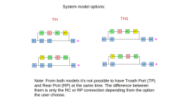
The closest models available are TH and TH1, and as you can see from attachment #3, we can't used TP and RP at the same time, user need to choose one or the other. In addition, having the offset connection between H1 and H2 don't help much in this case. Check attachment #4.
My proposal, with no impact in the hornresp interface, is to create a new model, maybe TH2 as suggested in the attachment #5.
As current defined in PM design, the port feeding the horn is so hollow and so close to the exit that looks like it works more as heat transfer then modifying the SPL response but with new Hornresp model we figure out and also to optimize this type of design.
Would you consider the possibility to create a new Hornresp model?
I saw the loudspeaker design people refers to as PM60 and PM90, as you can see from attachments #1 and #1. It makes me curious to check the SPL response but after having a CAD model and all inputs for hornresp I realized that with current models available it's not possible to simulate this design properly.
The closest models available are TH and TH1, and as you can see from attachment #3, we can't used TP and RP at the same time, user need to choose one or the other. In addition, having the offset connection between H1 and H2 don't help much in this case. Check attachment #4.
My proposal, with no impact in the hornresp interface, is to create a new model, maybe TH2 as suggested in the attachment #5.
As current defined in PM design, the port feeding the horn is so hollow and so close to the exit that looks like it works more as heat transfer then modifying the SPL response but with new Hornresp model we figure out and also to optimize this type of design.
Attachments


Hey fellas, How would we go about describing two of the passive radiators(in the same box with one driver) to horn response ? Double ‘Sd’ and ‘mms’ ?
Attachments
Last edited:
Hi David,
Looks like the order of the attachments was changed, so to translate:
Attachment #1 = PM90 and PM60.jpeg
Attachment #2 = PM Layout.png
Attachment #3 = Current TH System Model options.png
Attachment #4 = Avoinding Lossing one segment.png
Attachment #5 = New System Model Proposal.png
Best regards,
Looks like the order of the attachments was changed, so to translate:
Attachment #1 = PM90 and PM60.jpeg
Attachment #2 = PM Layout.png
Attachment #3 = Current TH System Model options.png
Attachment #4 = Avoinding Lossing one segment.png
Attachment #5 = New System Model Proposal.png
Best regards,
Would you consider the possibility to create a new Hornresp model?
Hi Marcelo,
Unfortunately my circumstances changed significantly a few months ago and I can no longer devote the time to Hornresp that I once did. Your proposed TH2 model would take a lot of work to implement - I will have a look when I get a chance but if I do decide to proceed don't expect to see anything for quite a while.
Kind regards,
David
How would we go about describing two of the passive radiators
The Hornresp Help file is your friend:
I will have a look when I get a chance
Hi David,
Thank you, I can image your situation, mine also changed a lot, I'm with a new born of 2 months.
Whenever is the right time I'm always grateful for your effort.
Regards,
Marcelo
I'm with a new born of 2 months.
Congratulations!
Would you consider the possibility to create a new Hornresp model?
Hi Marcelo,
I have now had a look at how much work would be required to fully integrate your suggested TH2 model into Hornresp and unfortunately it is very unlikely that I will be able to find the time to do so. I suspect that it will be pretty much just bug fixes from now on.
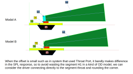
All is not lost however as I think that you should be able to get a reasonable idea of how the loudspeaker design you showed will perform by simply using the existing CH1 model with the path length set to zero. The port outputs in your speaker are almost at the horn exit and are relatively small compared to the mouth size, so any inaccuracies introduced by disregarding the offset and assuming two co-located point sources should not be overly significant, as demonstrated by the comparison I have included. An added bonus of using the CH1 model would be that it is then possible to also allow for the offset driver at the horn throat.
Attachment 1 shows the TH model representing your design with offset driver but without the throat port.
Attachment 2 shows the CH1 model representing your design with offset driver but without the throat port. The mouth port is specified using Horn 2.
Attachment 3 compares the results of the Attachment 1 and Attachment 2 models. The grey trace show the TH response and the black trace shows the CH1 response.
Attachment 4 shows the CH1 model representing your design with offset driver and throat port. This is the one to use for your simulations.
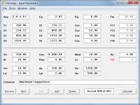
The input parameters for the above three models are given in Attachments 5 to 7.
Kind regards,
David
Attachments

the port feeding the horn is so hollow and so close to the exit that looks like it works more as heat transfer then modifying the SPL response but with new Hornresp model we figure out and also to optimize this type of design.
It would not be possible to do the above optimisation using the suggested CH1 model but the general effect of changing the port offset position relative to the horn mouth could be observed by adjusting the L45 slider in the TH model with S4 set to Auto. In the image below the grey baseline trace is for an offset from the mouth of 4 cm and the pink/red trace is for an offset of 10 cm.
general effect of changing the port offset position relative to the horn mouth could be observed by adjusting the L45 slider in the TH model with S4 set to Auto
Hi David, yes it gives an indication, hornresp is amazing. If we want to observe the effect of adding Throat Chamber and Throat Port we can do it too in a stand alone process as you did, the problem is to combine them acoustically in a meaningful way.
The other advantage of a new model is to check not only the placement of the port but also different Port area and Port length.
As you mention, it's too much work, let it for a future and just add it in the wish list, I'm just a very curious person.
When you vented the rear chamber, you switched the enclosure from a BP6S TH to a BP6P CH.
That might be a BP8P enclosure since you technically have the rear port and throat port venting into the the horn port.


That might be a BP8P enclosure since you technically have the rear port and throat port venting into the the horn port.
Unfortunately the effects of stuffing on the displacement are not included in this window as they are in the previous one.As you have shown by your example it is already possible to determine the value of maximum displacement reasonably accurately simply by direct observation. If a more precise value and the frequency at which it occurs is required then they can be found by sampling on the main window. Just click somewhere near the maximum and then use the left and right arrow keys to find the peak value, as illustrated in the second image below.
I would prefer not to complicate things further by adding the suggested feature. In other words, it's not going to happen 🙂.
[snip]
View attachment 1381915
Unfortunately the effects of stuffing on the displacement are not included in this window as they are in the previous one.
I don't understand why just looking at the Loudspeaker Wizard result doesn't allow you to determine the displacement accurately enough. If it is important to you then perhaps copy a screen print of the chart into Word and use the Zoom feature to make it easier to estimate the maximum value by simple scaling.
Hornresp Update 5640-241124
Hi Everyone,
CHANGE
Sound velocity and air density values can now be specified by the user.
Kind regards,
David


Hi Everyone,
CHANGE
Sound velocity and air density values can now be specified by the user.
Kind regards,
David
- Home
- Loudspeakers
- Subwoofers
- Hornresp