But Ubuntu touch only work on this
Not hmd
Asus Zenfone Max Pro M1
* F(x)tec Pro1 X
* Fairphone 3 and 3+
* Fairphone 4
* Google Pixel 3a and 3a XL
* JingPad A1
* Oneplus 5 and 5T
* OnePlus 6 and 6T
* Sony Xperia X
* Vollaphone
* Vollaphone X
* Vollaphone 22
* Vollaphone X23
* Xiaomi Poco X3 NFC / X3
Not hmd
Asus Zenfone Max Pro M1
* F(x)tec Pro1 X
* Fairphone 3 and 3+
* Fairphone 4
* Google Pixel 3a and 3a XL
* JingPad A1
* Oneplus 5 and 5T
* OnePlus 6 and 6T
* Sony Xperia X
* Vollaphone
* Vollaphone X
* Vollaphone 22
* Vollaphone X23
* Xiaomi Poco X3 NFC / X3

Hi!
Is there a way to simulate larger horns than Hornresp normally allows?
If I want to use an area larger than 99999.99 sq cm is there a way to do that?
Can I change units to meters in some setting somewhere to get around this?
Or can I get rid of the decimals to use larger values?
I know it might not be common or even reasonable to build horns this large but I think from an academic point of view or just from curiosity "what if", it would be very interesting to not have this limitation!
So you want a larger mouth than 10 square meters? 102 square feet? For real? That would give you nearly ripple free response to under 20 hertz anywhere on the ground. With a little ripple you could do 10 hertz. Inside a building 5 hertz with a little ripple.
I have been looking at a in room corner horn that approaches the 102 square feet limit. Would be nice if the limit was a little larger.
Is there a way to simulate larger horns than Hornresp normally allows?
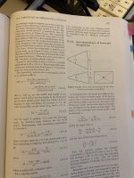
If the flare type is Hyp or Lec then S2 can have a maximum value of 999999.9 cm^2, meaning that the mouth area can then be up to 100 square metres or 1076 square feet.
For your Exp example (the same as for Hyp with T = 1), the difference in power response with a mouth area of 99999.99 cm^2 (grey trace) compared to 999999.9 cm^2 (black trace) is shown below.
Would be nice if the limit was a little larger.
Apart from S2 for Hyp and Lec single segment horns, it's not going to happen.
I know it might not be common or even reasonable to build horns this large but I think from an academic point of view or just from curiosity "what if", it would be very interesting to not have this limitation!
Setting Ang = 0.0 x Pi specifies an infinite length horn, meaning that the mouth size will be infinite also.
For your Exp example (the same as for Hyp with T = 1)
The compression ratio for your example with two drivers is greater than 10:1, which is really too high for a practical low-frequency horn.
That driver will shred to pieces at the 1st note...
The cone will vaporize
With a 10:1 ratio
Btw what was the bertha ratio ? Cause some drivers cones shred in that cabinet.
As I have read , can't remember what drivers
So a high BL means strong motor right ?
But the cone material must endure a strong motor correct ?
Otherwise you will have a shattered cone in no time under a high compression ratio.
Jbell stadium Horn and SS15 both have ratios around 1.65:1 so the 3015LF survive although their weak cone.
Yes?
Last edited:
Ah! Thanks a lot for this input!The compression ratio for your example with two drivers is greater than 10:1, which is really too high for a practical low-frequency horn.
Do you have any tips or formulas for how to calculate a suitable compression ratio for a given driver in a given situation?
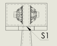
My plan was to mount the woofers in a force cancelling configuration creating a pressure chamber between the woofer before the air pressure enters the horn.
Is this a good idea? Am I simulating it correctly or do I need to add something to take into account the effect of the chamber between the drivers?
Attachments
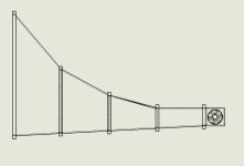
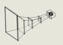
I'm not sure if I really want to create it physically. I would mainly like to see what kind of size it would take to get directivity down to 20 - 30Hz...So you want a larger mouth than 10 square meters? 102 square feet? For real? That would give you nearly ripple free response to under 20 hertz anywhere on the ground. With a little ripple you could do 10 hertz. Inside a building 5 hertz with a little ripple.
S2 = >1/3 of Sd.Ah! Thanks a lot for this input!
Do you have any tips or formulas for how to calculate a suitable compression ratio for a given driver in a given situation?
My plan was to mount the woofers in a force cancelling configuration creating a pressure chamber between the woofer before the air pressure enters the horn.
Is this a good idea? Am I simulating it correctly or do I need to add something to take into account the effect of the chamber between the drivers?
Some thoughts here: My approach to bass horn designAh! Thanks a lot for this input!
Do you have any tips or formulas for how to calculate a suitable compression ratio for a given driver in a given situation?
If the flare type is Hyp or Lec then S2 can have a maximum value of 999999.9 cm^2, meaning that the mouth area can then be up to 100 square metres or 1076 square feet.
For your Exp example (the same as for Hyp with T = 1), the difference in power response with a mouth area of 99999.99 cm^2 (grey trace) compared to 999999.9 cm^2 (black trace) is shown below.
View attachment 1342724
View attachment 1342725
Thanks a lot for the answer I will look into it!
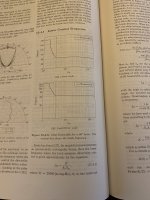
I was wondering if you could help me with the formula (15.4.1) mentioned in the book "High-Quality Horn Loudspeaker Systems" attached below.
I do not seem to be able to use this formula correctly and get consistent results that match with the "Beam Width" plot in Hornresp.
In the formula fB is the break frequency when the horn stops being directive, K is a constant of 25000 that much I understand.
But how to input Theta_i (the coverage angle) and especially Dm is a bit confusing.
In the book Dm = "the dimension of the mouth in meters".
But it doesn't say if this is the diameter, the circumference or some other distance and I have tried putting in some of these with little luck of them matching the Hornresp result.
Attachments
To Kolbrek:
Those blogs are impressive ,
I was reading some but most of the stuff is beyond my pay grade 🙂
Those blogs are impressive ,
I was reading some but most of the stuff is beyond my pay grade 🙂
I think I got the formula working now.Thanks a lot for the answer I will look into it!
I was wondering if you could help me with the formula (15.4.1) mentioned in the book "High-Quality Horn Loudspeaker Systems" attached below.
I do not seem to be able to use this formula correctly and get consistent results that match with the "Beam Width" plot in Hornresp.
In the formula fB is the break frequency when the horn stops being directive, K is a constant of 25000 that much I understand.
But how to input Theta_i (the coverage angle) and especially Dm is a bit confusing.
In the book Dm = "the dimension of the mouth in meters".
But it doesn't say if this is the diameter, the circumference or some other distance and I have tried putting in some of these with little luck of them matching the Hornresp result.
At least if I assume a conical square horn and use the width of the mouth as Dm it seems to work kind of reliably.
The formula works best for conical horns, and gives the frequency where the horn is large enough to to reduce the beamwidth to the specified angle. I haven't used it much for other horn shapes than some form of conical constant directivity, but it should have some relevance for other horn shapes too. D is either the mouth width (or height, depending on which plane you are designing for) for rectangular horns, or mouth diameter for circular horns. The factor K is different for the two cases, and both are given on page 575.
The beamwidth calculation for conical horns (and OSWG I think) in Hornresp is reasonably good. For other horn shapes a different model is used that is not as accurate.
The beamwidth calculation for conical horns (and OSWG I think) in Hornresp is reasonably good. For other horn shapes a different model is used that is not as accurate.
Can those principles be used to design PA subs, I'm not really in to HT audio but want to make a high SPL PA system with high efficiency sub cabinets.
Is it possible to have 4 horn loaded cabinet with premium PA drivers that can wipe the floor of 8 double 18's?
Eyes on RCF LN19S400
I wish they stick in a 5" coil but it is a 4"
Specs below
https://www.rcf.it/en/products/product-detail/ln19s400
Is it possible to have 4 horn loaded cabinet with premium PA drivers that can wipe the floor of 8 double 18's?
Eyes on RCF LN19S400
I wish they stick in a 5" coil but it is a 4"
Specs below
https://www.rcf.it/en/products/product-detail/ln19s400
FYI/FWIW, the pioneers apparently concluded that a reactance annulled BLH was best overall performer with baffle size dictating its low corner/cut-off. Note 'open' rear chambers: https://www.lansingheritage.org/images/altec/catalogs/1942/page09.jpg
- Home
- Loudspeakers
- Subwoofers
- Hornresp