And there is one point that I need to check with David McBean
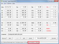
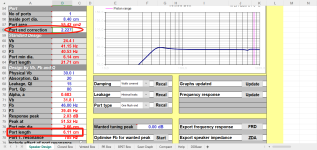
In Attachment 1, because Ap and Lpt are used Hornresp knows that a 20 cm long port tube having a cross-sectional area of 100 cm2 is being specified, and so an internal unflanged end correction of length 3.46 cm is added automatically.
Unflanged end correction = 0.1952 * Pi * [port tube radius] = 0.1952 * Pi * 5.64 = 3.46 cm
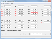
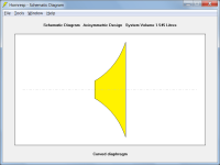
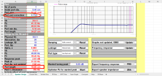
In Attachment 2, Hornresp has no way of knowing that horn segment 3 is to be treated as a port tube and so no end correction is automatically added. An end correction of 3.46 cm has been added manually to L34 (20 + 3.46 = 23.46) so that the results for the two designs are effectively the same when compared, as shown in Attachment 3.
Note that it is only necessary to add a correction to the internal end of the port tube, as the radiation impedance is taken into account at the external end.
Attachments

RCF bass drivers are quite often curvilinear, and it goes against common sense.
A curvilinear diaphragm will normally be more structurally rigid than a simple flat surface cone diaphragm, flexing less under high air loads.
Curvilinear diaphragms can also be used in midrange drivers, to influence directivity.

The yes was meant for the new RCF drivers being curvilinear.
@David McBean
I am afraid this explanation is somehow incomplete or insufficient.
As when we make a cone that opens wider, it obviously and provably succumbs to the force pushing on it. The deeper the cone is, the stronger it holds to a some point that would be extreme for a speaker design. And so in corvilinear design, the more flat cone at its edges seem to be weaker. Touching on the side of such cone somewhat proves that, as the edge of the cone is flexing some more. That leaves me somewhat untrusting and baffled.
The point also seemingly supports that view, as the midrange drivers with such shaping somewho enjoy the qualities of gradual decoupling towards the stiffer center to widen the radiation pattern with frequency.
Hi, where do I get the p0c0 term in the below equation?Some thoughts here: My approach to bass horn design
If I want to calculate a suitable St (or S1) from the B&C 21DS115 driver with a Bl = 28, Sd =1680, Re =2.2 how would I go about it?
And what is the "Rg" term in the equation?
Also generally will allow a driver to reach a little higher in frequency response. Although that is also linked to the dust cap diameter and height, or radius how ever you choose to view the profile. Basically if you cannot easily deform the cone via hand pressure you have a cone that is rather robust. Hornresp calculates the cone surface area air pressure. That was asked for and added when I was first getting my knocks in a higher pressure horn subwoofer. Proved to be useful.A curvilinear diaphragm will normally be more structurally rigid than a simple flat surface cone diaphragm, flexing less under high air loads.
Curvilinear diaphragms can also be used in midrange drivers, to influence directivity.
Greg,
You are old enough to remember the cones from the 70's and 80's. As thin and as light as possible. Those definitely are not the types to withstand higher pressure. What we have been getting from the Pro-sound suppliers B&C Faital Pro, BMS, Beyma are much tougher cones. And they are usually the drivers that are best suited to a high compression ratio horn.
You hit the test criteria exactly. Try and flex the cone. Some cones are amazingly stiff at the surround junction. That is a cone that is suitable for a higher compression horn.The yes was meant for the new RCF drivers being curvilinear.
@David McBean
I am afraid this explanation is somehow incomplete or insufficient.
As when we make a cone that opens wider, it obviously and provably succumbs to the force pushing on it. The deeper the cone is, the stronger it holds to a some point that would be extreme for a speaker design. And so in corvilinear design, the more flat cone at its edges seem to be weaker. Touching on the side of such cone somewhat proves that, as the edge of the cone is flexing some more. That leaves me somewhat untrusting and baffled.
The point also seemingly supports that view, as the midrange drivers with such shaping somewho enjoy the qualities of gradual decoupling towards the stiffer center to widen the radiation pattern with frequency.
Well, these RCF drivers I had, weren't THAT. Not that stiff at the edge, and I would trust B&C speakers cone somewhat more.
Now, I remember the good vid about that:
It looks horrific for the cone to work in such mode repeatedly. I wonder if it is visible in normal use.
Now, I remember the good vid about that:
It looks horrific for the cone to work in such mode repeatedly. I wonder if it is visible in normal use.
Hi, where do I get the p0c0 term in the below equation?
If I want to calculate a suitable St (or S1) from the B&C 21DS115 driver with a Bl = 28, Sd =1680, Re =2.2 how would I go about it?
And what is the "Rg" term in the equation?
View attachment 1343831
p0 = density of air
c0 = velocity of sound
Rg = amplifier output resistance
Given:
p0 = 1.205 kilograms per cubic metre
c0 = 344 metres per second
Bl = 28.8 tesla.m
Sd = 1680 cm2
Re = 2.2 ohms
Rg = 0 ohms (for constant voltage amplifier)
Nd = 2P
S1 = (Re + Rg) * Sd ^ 2 * p0 * c0 / Bl ^ 2
Then:
S1 = (2.2 / 2 + 0) * (1680 * 2 / 10000) ^ 2 * 1.205 * 344 / (28.8 ^ 2) * 10000 cm2
S1 = 620.63 cm2
Compression ratio = (1680 * 2) / 620.63 = 5.41
I am afraid this explanation is somehow incomplete or insufficient.
In what way is the explanation incomplete or insufficient?
The excerpt shown below has been taken from the classic reference text "Acoustical Engineering" by Harry F Olson. In the author's words:
"The flared shape is somewhat more rigid than the conical shape. For this reason, the directional pattern in the high-frequency range is very much sharper."
Pretty much what I said…
Touching on the side of such cone somewhat proves that, as the edge of the cone is flexing some more.
To truly and accurately test for rigidity, pressure needs to be applied across the entire surface area of the diaphragm, as occurs under normal operating conditions. Exerting a point force on a small section of the cone does not achieve this.
Well this should be obvious I thought. Pushing at the paper more "from side" will make it crumble easier. If we do not know angles and sizes, then even mr.Olson is not right. It's the same thing as pushing on deep cone or very shallow one. The funny thing is I ignored was the push in the opposite direction. Mean pulling. At that time the design has really hard time not crumbling.
Pushing at the paper more "from side" will make it crumble easier. If we do not know angles and sizes, then even mr.Olson is not right. It's the same thing as pushing on deep cone or very shallow one.
Not sure that I understand the point you are making, although I would be very surprised indeed if Olson got it wrong, given his background and experience:
https://en.wikipedia.org/wiki/Harry_F._Olson
If the driver front air volumes indicated in yellow in the attachments are pressurised, then the straight surface of the diaphragm in Attachment 1 is going to deform at a lower pressure than the more rigid convex curved surface of the diaphragm in Attachment 2.
Attachments

Thank you so much!p0 = density of air
c0 = velocity of sound
Rg = amplifier output resistance
Given:
p0 = 1.205 kilograms per cubic metre
c0 = 344 metres per second
Bl = 28.8 tesla.m
Sd = 1680 cm2
Re = 2.2 ohms
Rg = 0 ohms (for constant voltage amplifier)
Nd = 2P
S1 = (Re + Rg) * Sd ^ 2 * p0 * c0 / Bl ^ 2
Then:
S1 = (2.2 / 2 + 0) * (1680 * 2 / 10000) ^ 2 * 1.205 * 344 / (28.8 ^ 2) * 10000 cm2
S1 = 620.63 cm2
Compression ratio = (1680 * 2) / 620.63 = 5.41
I must say I am really impressed with all the help and dedication you provide at this forum and the more I learn about Hornresp I realize more and more what a great software it is!
However I also realize my knowledge gaps and that I might have had a slightly simplistic view of the problem...
All of the large signal properties are not captured in the Thiele/Small parameters (and therefore not included in any simulation, even FEM simulations mostly ignore them if you do not construct a full multi-physics model with included material properties) and many loudspeaker manufacturers don't even publish all of their material choices for cone materials or the exact geometrical shape of the cone.
So in the example of my intended driver the impedance match would be a compression ratio of 5.41.
But you say that this is too much and the cone will not survive that?
Is it best to just follow some rules of thumb and general experience and keep the CR below 3 or maybe up to 4 or is there a way to calculate a more suitable compression ratio?
I would guess not unless I want to dive into the material properties of the driver and try to somehow reverse engineer it?
Does this impedance mismatch matter?
I guess it will give a bit more reflections and ripple but maybe that is not a big deal?
Or should I strive to match the throat and driver?
If I increase Rg with a resistor does that do anything useful or does it just introduce unnecessary losses to the system?
Also from what I have read a strong motor with high Bl should be a good thing for cone control and make that driver suitable for a horn-loaded system.
But if the Bl is so high so that the optimal impedance match with the horn always leads to such a high compression ratio so that the cone can't handle it, then is that still a suitable driver for horn loading or should I look for a driver with lower Bl and a more balanced spec?
It is not possible to do directivity calculations on an infinite horn in Hornresp?Setting Ang = 0.0 x Pi specifies an infinite length horn, meaning that the mouth size will be infinite also.
I guess that it would be meaningless since you would always be inside the horn if it's infinite, but my main reason for wanting to go up in size was to explore what it would take to reduce bass in unwanted directions.
But my conclusion so far is that it would take a huge horn to get any directivity at low frequencies, so multiple subs and DSP is perhaps the only reasonable option...
The devil is in the detail.Not sure that I understand the point you are making, although I would be very surprised indeed if Olson got it wrong, given his background and experience:
https://en.wikipedia.org/wiki/Harry_F._Olson
If the driver front air volumes indicated in yellow in the attachments are pressurised, then the straight surface of the diaphragm in Attachment 1 is going to deform at a lower pressure than the more rigid convex curved surface of the diaphragm in Attachment 2.
You know ad absurdum how straight sheet of paper bends under its own weight. Now if you roll it into a cylinder and push on axis of the cylinder, the paper will crumble under much higher force than when pushed to the side/wall.
The edge of the curved cone is getting closer to its forces pushing flat on the material that is not very sturdy in that direction, and relies on the counter-contraction forces. Otherwise it would crumble. It is very simple physics.
Where it gets less simple is on the speaker cone, where force pushes from both sides and both sides are attached to other stuff.
I guess it is matter of particular design. Weight, steepness, other aspects. Also manufacturers will have their studies in their hands. Would love to see these.
B&C speakers subwoofers are known for their robustness in design. Maybe they sort it out with tad larger dustcap, heavier cone and other ways in their disposal.
Yeah they are! 😀B&C speakers subwoofers are known for their robustness in design. Maybe they sort it out with tad larger dustcap, heavier cone and other ways in their disposal.
No SH! 🙂
Yes, standing on the "paper cone" tells a lot about the sturdiness of a solution. It should crumble, but it doesn´t. And when you touch it by just one finger, it looks like it CANNOT withstand any serious force. But then you think what amplifiers they use for it, and you think even more this can´t be true.
On the IPAL coil and cone, there are certainly forces in excess of 1000N pushing at times. You would say former has to disconnect from the cone, the coil must slip or the cone has to go in half, or something has to frikkin give. No. It holds for milions of repetitions. Wow. Just WOW.
I am very weirded out by how RCF and B&C are solving technical designs of their products so differently. They are different. A LOT. To a point one could think that one company is simply wrong. But both ways work. B&C showed its prowess in design and math, RCF often solves it with bigger hunk of metal or magnet, yet stays light and fully functional with such great performance that I buy them as much still. Curved or flat, I am happy that none of that failed me to date.
Great moment by the way, Benett provides great info about the products, technology in industry and such. Always happy to see a new YT release. Maybe getting him the wine he likes (and mr.McBean)will be added to my todo list. Just an idea while sipping lovely port and simulating in HR...
Last edited:
All of the large signal properties are not captured in the Thiele/Small parameters (and therefore not included in any simulation, even FEM simulations mostly ignore them if you do not construct a full multi-physics model with included material properties) and many loudspeaker manufacturers don't even publish all of their material choices for cone materials or the exact geometrical shape of the cone.
The T/S parameters are small signal parameters after all. What you need for large signal simulation is really the Klippel LSI data, that shows how Cms, BL, Le etc varies with displacement. And then a simulator that will take those parameters and give you distortion curves. But even that won't give you any info on how much back pressure the cone can withstand. But Hornresp calculates the force on the cone, so you could of course do some (destructive) testing.
So in the example of my intended driver the impedance match would be a compression ratio of 5.41.
But you say that this is too much and the cone will not survive that?
Is it best to just follow some rules of thumb and general experience and keep the CR below 3 or maybe up to 4 or is there a way to calculate a more suitable compression ratio?
I would guess not unless I want to dive into the material properties of the driver and try to somehow reverse engineer it?
Does this impedance mismatch matter?
I guess it will give a bit more reflections and ripple but maybe that is not a big deal?
Or should I strive to match the throat and driver?
The exact impedance match isn't critical, but it does provide smoother response if the throat impedance varies a lot (like if the horn mouth is to small, i.e. CIR much less than 0.7). The impedance match is also the condition for highest sensitivity.
Another factor in deciding the throat area is air distortion, which increases the more power per area you put into the horn. So a small throat has higher distortion. Hornresp gives an estimate of air distortion too.
If I increase Rg with a resistor does that do anything useful or does it just introduce unnecessary losses to the system?
Don't do that, it just wastes power. And if you're at a lever where you're worried about the cone tearing, you'll waste lots of power. But you could add some negative current feedback to increase the amplifier output impedance.
Also from what I have read a strong motor with high Bl should be a good thing for cone control and make that driver suitable for a horn-loaded system.
Yes and no, because there is no absolutes and it all depends on your application. High BL gives a high efficiency-bandwidth ratio, and is often used as a figure of merit. But if you don't need the bandwidth (for a subwoofer for instance), you can get high efficiency in a limited bandwidth with lower BL. A smaller throat area pushes the upper corner frequency upwards, which you don't really want for a subwoofer.
But if the Bl is so high so that the optimal impedance match with the horn always leads to such a high compression ratio so that the cone can't handle it, then is that still a suitable driver for horn loading or should I look for a driver with lower Bl and a more balanced spec?
It may still suitable for horn loading, but maybe not for pushing the power output to the limits.
But instead you can select a throat area based on a more gentle compression ratio (1.5-3) and calculate what BL (or BL^2/Re) you need for an impedance match, and then look for a driver with specs close to that.
In Attachment 1, because Ap and Lpt are used Hornresp knows that a 20 cm long port tube having a cross-sectional area of 100 cm2 is being specified, and so an internal unflanged end correction of length 3.46 cm is added automatically.
Thanks David, but... I am getting a bit confused here.
I actually thought, as stated in another thread. that the mentionned end correction at the bottom (the 3.46cm in your example) was already calculated/integrated/comprised in the port length specified in Lpt.
See the thread i am taking about here : https://www.diyaudio.com/community/...p-and-end-corrections-for-port-length.382053/
So, to make things clear once and for all : when constructing the cabinet, should the port's physical length be 20cm or 23.46cm ?
Unflanged end correction = 0.1952 * Pi * [port tube radius] = 0.1952 * Pi * 5.64 = 3.46 cm
In Attachment 2, Hornresp has no way of knowing that horn segment 3 is to be treated as a port tube and so no end correction is automatically added. An end correction of 3.46 cm has been added manually to L34 (20 + 3.46 = 23.46) so that the results for the two designs are effectively the same when compared, as shown in Attachment 3.
Note that it is only necessary to add a correction to the internal end of the port tube, as the radiation impedance is taken into account at the external end.
Ok, so now lets say that I want to do a rectangular slot port, with the internal bottom and side panels acting as three of the port's sides.
For what I've heard in many places including this forum, a slot port in this case should be physically much shorter because the side and bottom panels already act as an extension of the port.
Such a difference can be easily seen in the example in the two attachements taken from Unibox, where all numbers are strictly the same, except for the port, where in one the port is a round tube flanged at one end - with a K of 0.732, and in the other the port is supposed to be a slot port with K of 2.227 we can see that diffence in port length is quite substantial.
So do you have a specific formula that should be applied in hornresp to calculate port end correction in the case of such a slot port, or should I just use the length of the last section of my MLTL as mentionned in hornresp as the true physical length of my port (--> meaning here the length of the fourth panel of the vent, the one that is not a cabinet side or bottom) when building the cabinet ?
Sorry to bother you with this David, but I can't seem to find any clear and definite answer to this question anywhere really, and I have been wondering about this for quite a while now.
Many many thanks !
Attachments
- Home
- Loudspeakers
- Subwoofers
- Hornresp