Programmatically working out a taper rate is proving to be a challenge.
After playing around with Hornresp for a while, it looks like it's fairly easy to get the required length of a tapered TL given F6H (the approximate frequency at which the next resonance will be out of phase with the driver, using the following equations:
Given F6H>6*Fb
L=6*c*100/(4*F6H) (cm), where c=speed of sound (m/s)
And you can get the average CSA of the TL from that
CSA=Vb*1000/L (cm^2)
The problem here is how to use the above information to adjust the taper of the TL along its path so that the Helmholtz resonance of the TL works out to be Fb. I have a few ideas about how to address this which I'll look at later.

Hi Giri, GM and Brian,
Thanks for all the information. It seems that we can get different answers depending on which set of rules we choose to adopt 🙂.
I have compared Martin's 2006 and 2021 methods and it seems that the 2006 method produces the better results. With the same driver, taper rate of 0.2 and no driver offset, Attachment 1 shows the result obtained using the 2006 method and Attachment 2 shows the result obtained using the 2021 method.
Interestingly, in working through the 2021 paper I think that I may have found an error. Martin calculates the taper volume using the formula:
Vb = 0.5 * (S0 + SL) * L
This assumes that the cross-sectional area tapers linearly, but it is the radius, not the area, that actually tapers linearly. The correct formula to use for an axisymmetric conical segment is:
Vb = Pi * L * (R0 ^ 2 + R0 * RL + RL ^ 2) / 3
Kind regards,
David
The fundamental premise is to design the line close to the driver fs such that the original impedance graph that has a high peak at fs would be transformed to a graph that has two smaller impedance peaks distributed symmetrically about the fs. This was the explanation given by Martin King when I asked him as a total newbie. I still follow this principle as an easy method to arrive at a good first guess.
I'd guess which ever method gets close to driver fs would be the superior one.
Looks like the equivalent of a "Boom Box" alignment for a vented enclosure (Fs=Fb, adjust Vb to suit).The fundamental premise is to design the line close to the driver fs such that the original impedance graph that has a high peak at fs would be transformed to a graph that has two smaller impedance peaks distributed symmetrically about the fs. This was the explanation given by Martin King when I asked him as a total newbie. I still follow this principle as an easy method to arrive at a good first guess.
I'd guess which ever method gets close to driver fs would be the superior one.
I'm guessing that, like the "Boom Box" alignment for vented enclosures, that approach will lead to non-flat passband response for Qts > 0.37.
Looks like the equivalent of a "Boom Box" alignment for a vented enclosure (Fs=Fb, adjust Vb to suit).
I'm guessing that, like the "Boom Box" alignment for vented enclosures, that approach will lead to non-flat passband response for Qts > 0.37.
If I remember correct, Martin King also explained that a vented enclosure has acoustic capacitance dominating the impedance at the tuning frequency and a TL has acoustic inductance dominating (hence, a tapered TL is shorter for the same fundamental frequency). But fundamentally, they belong to the same "family", so to say. My memory might be dodgy through.
edit: for clarity
Assuming it is possible to calculate the TL length for a given taper rate, is also possible to then calculate the Helmholtz resonance frequency?The problem here is how to use the above information to adjust the taper of the TL along its path so that the Helmholtz resonance of the TL works out to be Fb.
If so, then Hornresp could determine the taper rate and length required to give a resonance frequency equal to Fb iteratively.
Well, the length of the tapered TL is basically set for a given F6H using the equation I gave above, and Vb and Fb remain the same as that of the straight TL. Is this enough information to determine the taper rate iteratively?Assuming it is possible to calculate the TL length for a given taper rate, is also possible to then calculate the Helmholtz resonance frequency?
If so, then Hornresp could determine the taper rate and length required to give a resonance frequency equal to Fb iteratively.
Right, at Fs the impedance peaks of a vented alignment will be at the same amplitude, though not always symmetrically placed IME, so for me an easier way when simming is to look at the displacement graph, i.e. when the dip hits Fs I'm done and for sealed it's at the box tuning's single impedance peak.The fundamental premise is to design the line close to the driver fs such that the original impedance graph that has a high peak at fs would be transformed to a graph that has two smaller impedance peaks distributed symmetrically about the fs.
Can F6H be calculated automatically, rather than the user being required to enter a value?the length of the tapered TL is basically set for a given F6H using the equation I gave above
Can the Helmholtz resonance frequency be calculated given the length and taper rate?Is this enough information to determine the taper rate iteratively?
a thought (and a little more … 😝) bare with me…
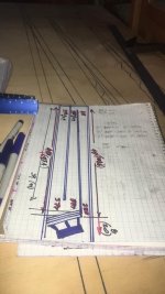
“π÷9 = 0.349
this entry point promotes Helmholtz resonance. having the driver entry perfectly at this point facilitates the harmonics with double and triple the wavelength of the fundamental, especially when the TL has 2 folds (3 sections), which causes reinforcement of the fundamental through harmonic subtraction. the reinforcement is perceived as the difference between the double and triple wavelength and thus our ear hears an additional 'ghost' fundamental, or rather a boost of that frequency. the frequencies in the box are not 'fighting' each other but rather coalescing on every node in the TL. it's like the Tacoma Narrows bridge, resonance became so strong the entire structure started waving. this is ideally what one would want, smaller-scale, in a TL”
is this represented? considered or part of the inner workings of horn response?
One things for sure I can get a 300 cm ODTL to ‘ perfectly align ‘ with 86.0 Hz
using 104.72 and 195.28 as the split. 300x (pi/9) .
100/200/300 cm as 104.72, 209.44,314.16 , 14.16 cm outside of the ‘qw pipe’ is the velocity max? makes sense from where I’m standing.
This is what seems to make this work.
1200 cm as 7.2 hz
300 cm as 28.8 hz (1/4 harmonic )
100cm as 86.4 hz (3 x 1/4 h)
60cm as 144 hz (5 x 1/4 h)
further enforcing the potential here for accuracy (and ultimately credit to horn response) is the pHone (phi? ironically?) mode where you find the same exact numbers effective ly canceled out The higher up you go outside of the passband at log 10 or 100 scale. when you perfectly align 270 cm against 90 and offset both sides at 30cm. that is one of many interesting combinations that result in a very peculiar scenario that flags frequencies at -990dB If and when you hit the right combination of things that truly do align cross-sectional area and lengths between landmarks established by input values.
Anyone interested in measured and real electrical impedance response curves of a similar cabinet in pH one…^^^^ as the above paragraph discusses, those exist as well as an increasing number of additional
Looking further into this and with the assistance of some people who in math and science skills would rival/equal almost anyone in this group (guessing ?) and certainly make me look like a fool, find the results of what horn response presents as both remarkable relevant and highly impressive. that’s an electronically engineer for PG /E and astronomer And Astro photographer, combining heads to look at things independent of any loudspeaker building concepts to which they were ignorant , until now.
Attachments
-
 02318FB3-F86E-4F5C-A076-F952B7571B23.jpeg64.2 KB · Views: 121
 -
 B95080F3-D717-4009-9E68-B7B32E97A8AE.jpeg136.8 KB · Views: 102
 -
 E775B755-726F-45C5-B0BD-7CA9090B235A.jpeg61.9 KB · Views: 103
 -
 39B21B30-5BF7-46A6-BB0C-755D824F06FF.jpeg483.3 KB · Views: 111
 -
 BBEF5C7E-B53D-470E-995C-F10AE64D5CCB.png92.1 KB · Views: 105
I think an extra parameter will need to be provided to generate a tapered TL with a specific Vb and Fb. This could either either the taper rate, the path length or the upper cutoff frequency, or perhaps the ratio of mouth size to driver Sd. Perhaps the last parameter is the best one to go with.Can F6H be calculated automatically, rather than the user being required to enter a value?
It certainly seems that way. I had been hoping that it might have somehow been possible to determine an 'optimum' taper ratio from the inputs we already had. I am not sure where to go from here - based on the positive feedback received from GM perhaps it would be safest just to adopt Martin's original method, which appears to be reasonably well proven...I think an extra parameter will need to be provided to generate a tapered TL with a specific Vb and Fb.
Path length seems to be what people(builders) care about, practically.I think an extra parameter will need to be provided to generate a tapered TL with a specific Vb and Fb. This could either either the taper rate, the path length or the upper cutoff frequency, or perhaps the ratio of mouth size to driver Sd. Perhaps the last parameter is the best one to go with.
The problem is that the "optimum taper" depends on what it is you're actually trying to design. For a subwoofer, bandwidth is less important than linearity and output capability, because you're going to be filtering it ~80 Hz anyway. So a low, or even no taper is fine for an ODTL being designed for subwoofer duty. OTOH, for an ODTL geared towards use in a full-range system, pushing F6H up as high as practically possible makes sense, as the impact of harmonics at higher frequencies can be more easily minimized via internal damping of the enclosure.It certainly seems that way. I had been hoping that it might have somehow been possible to determine an 'optimum' taper ratio from the inputs we already had. I am not sure where to go from here - based on the positive feedback received from GM perhaps it would be safest just to adopt Martin's original method, which appears to be reasonably well proven...
"Optimum" taper can be defined as one that allows for the shortest line length while not resulting in port noise (exit velocity < 18 m/s)?The problem is that the "optimum taper" depends on what it is you're actually trying to design. For a subwoofer, bandwidth is less important than linearity and output capability, because you're going to be filtering it ~80 Hz anyway. So a low, or even no taper is fine for an ODTL being designed for subwoofer duty. OTOH, for an ODTL geared towards use in a full-range system, pushing F6H up as high as practically possible makes sense, as the impact of harmonics at higher frequencies can be more easily minimized via internal damping of the enclosure.
That might work for subwoofers, but not so much for full range systems, where reducing resonances emerging from the vent might be more important."Optimum" taper can be defined as one that allows for the shortest line length while not resulting in port noise (exit velocity < 18 m/s)?
FWIW, having been only able to calc a PR the long hand way, it became obvious I was better off designing TQWTs by calcing an Sd = vent/TL terminus with the alignment Vb = box + vent volume (auto calc'd by HR 👍) and taper a simple scale where max flat (~0.403 Qts' per Margolis-Small) was constant taper (MLTL) with inverse taper (TQWT) up to 20:1 CR for < ~0.403 Qts' and 1:20 CR for positive taper > ~0.403 Qts' (all types TL horns).
Note that ??? (Paul?) use to post regularly (memory's going pretty fast now), claimed success with up to 30:1 CR.
Note that ??? (Paul?) use to post regularly (memory's going pretty fast now), claimed success with up to 30:1 CR.
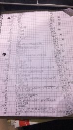
no taper: het Over it already?? it’s a quarter wave resonator. might even be three in series if you do it right. they might even support each other and the end result at the same time,(duh) This is far more effective once you start playing with it
s1-s2 (3x cm2) x L12 (104.72cm)
s2-s3 (3xcm2) x L23 (100 cm)
s3-s4 (x cm2 ) x L34 (95.28cm)
s1-s2 (3x cm2) x L12 (104.72cm)
s2-s3 (3xcm2) x L23 (100 cm)
s3-s4 (x cm2 ) x L34 (95.28cm)
The problem is that the "optimum taper" depends on what it is you're actually trying to design. For a subwoofer, bandwidth is less important than linearity and output capability, because you're going to be filtering it ~80 Hz anyway. So a low, or even no taper is fine for an ODTL being designed for subwoofer duty. OTOH, for an ODTL geared towards use in a full-range system, pushing F6H up as high as practically possible makes sense, as the impact of harmonics at higher frequencies can be more easily minimized via internal damping of the enclosure.
Tapered lines tend to be acoustic low-pass filters anyway....That might work for subwoofers, but not so much for full range systems, where reducing resonances emerging from the vent might be more important.
well then what are folds at node/anti node for 3 x 1/4 as well? assuming that’s done perfectly and intentionally. not just as driver entry alone..Tapered lines tend to be acoustic low-pass filters anyway....
- Home
- Loudspeakers
- Subwoofers
- Hornresp