WOW!!! Thank you so much DMB! Now, if I could only get this version on my work laptop...d@mn I T.
You wouldn't believe me if I told you how many hours it took 🙂.
Needless to say, there have been some very long "binge" coding sessions over the past few weeks, to get everything to work the way that I wanted it to...
I am 36 years out of coding. And you just described exactly why! I was not exactly gifted at it. I could geterdun. But the crazy long hours that are required when you are in the groove were my downfall. Oh and staring at a screen for hours and hours. I truly appreciate the skills and tenacity of yourself and a few other generous coders that take the time to imagine and understand what to do in order to make up these useful tools.
Countless sheets of MDF and Plywood are saved from a horrible death due to comprehensive simulations 😀
I have to chime in at this point.
Having used Hornresp a fair bit years ago when I created and refined my system, after a rest of several years, I am using again [emoji846] to create some Le Cléac'h profiles and test some simulations.
I'm incredibly grateful for the effort and dedication David (and other contributors?) has/have put into making it what it is.
Great resource for horn speculators and builders.

How I can file on my pc?
Hi tamra,
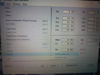
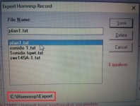
The exported file should be in the 'Export' sub-folder under the 'Hornresp' folder on your C: drive.
(The path to the file is shown at the bottom of the Export Hornresp Record form, as highlighted in the attachment).
Kind regards,
David
Attachments
There's some math here: http://www.xlrtechs.com/dbkeele.com...Preprint) - LF Horn Design Using TS Paras.pdf
.......and Prof. Leach's thoughts on the subject: http://www.xlrtechs.com/dbkeele.com...Preprint) - LF Horn Design Using TS Paras.pdf
In short, it can only be done to hyperbolic flares, so assume your horn isn't. 🙁
That said, Altec [the original] suggested that I tune the rear chamber using the mean between Fl and Fh and call it 'good enough'.
Fogot to include Prof. Leach's horn design theory paper 🙁: https://leachlegacy.ece.gatech.edu/papers/HornPaper/HornPaper.pdf
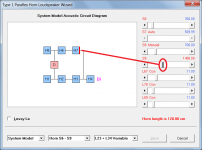
Just to clarify, S6, S8 are S9 are cross-sectional areas, not segments. The additional segments are designated as H5, H6 and H7.
S6 = H5 throat area
S7 = H5 mouth area and H6 throat area
S8 = H6 mouth area and H7 throat area
S9 = H6 mouth area
S7 is calculated automatically because there are only three area parameter values available to use as inputs. To be able to calculate S7 the flare types for segments H5 and H6 have to be the same.
This is amazing!! I have been geeking out with a youtuber who designs thermo acoustic engines abd cooling cycles using the sane principle in tubes(pipes).
giving it the full ‘beans’ workout and creating some rediculous versions of ‘paraflex’ that take previous models ive built or have saved as sims for a particular driver yo an absokte ideal phase aligned result.... some very intersting things happen when you can give a bit more explanation to that second chamber which essentially was just a two part csa/length, as vrc and ap/lp, and now has actual driver entry detail that was limited to only one sides pipe. Essentially now we have two pipes that can be set at a length (and folds) to which quite easily line up the distance from the closed end (each of them) to the imaginery point of ‘fulcrum/middle/apogee 🙂? ’ between them as seen in a thermo acoustical motor. Thats pressure phase in our speaker use but in the case of another application(youtubers who play with thermo acoustical heat and cooling results are now being introduced to your software as a result of the relationship there is between both systems.
IE: it would seem you can find the ideal location for the flame/wet towel and steel wool stuffing(pressure differential) which promotes the self timed and continuous running motor not unlike the sterling engines. Who woulda known?? This is hilariusly fun! Youre an amazing guy David, fertilizing everyones brains with opportunity to grow!
I am 36 years out of coding. And you just described exactly why! I was not exactly gifted at it. I could geterdun. But the crazy long hours that are required when you are in the groove were my downfall. Oh and staring at a screen for hours and hours. I truly appreciate the skills and tenacity of yourself and a few other generous coders that take the time to imagine and understand what to do in order to make up these useful tools.
Countless sheets of MDF and Plywood are saved from a horrible death due to comprehensive simulations 😀
Please save the mdf tree! its a rare wood grown only in small areas surrounding Chernobyl where it seems to flourish and produce the very best wood (and saw dust for glue/filler and strange boogers?)!! 😀
I updated my BOXPLAN-PARAC workbook to support the Hornresp "PH1" simulation model.
The next update will enable exported BOXPLAN paraflex designs to be imported direct into the loudspeaker wizard, similar to the existing "F6" functionality for other system types.
Should this be H7?Just to clarify, S6, S8 are S9 are cross-sectional areas, not segments. The additional segments are designated as H5, H6 and H7.
S6 = H5 throat area
S7 = H5 mouth area and H6 throat area
S8 = H6 mouth area and H7 throat area
S9 = H6 mouth area
S7 is calculated automatically because there are only three area parameter values available to use as inputs. To be able to calculate S7 the flare types for segments H5 and H6 have to be the same.
Should this be H7?
Hi SamAnytime,
It should indeed be H7. Thanks for making me aware of the error, my apologies for any confusion caused.
Kind regards,
David
Attachments
is there a PAYPAL or similar means to connect with
HORNRESP specifically and at random like buying a coffee or a beer for a coworker, friend, a casual not formal thanks, etc
HORNRESP specifically and at random like buying a coffee or a beer for a coworker, friend, a casual not formal thanks, etc
is there a PAYPAL or similar means to connect with
HORNRESP specifically and at random like buying a coffee or a beer for a coworker, friend, a casual not formal thanks, etc
yep DM you need this on the site
Buy Me a Coffee
This has been suggested many times over the years. David has always politely declined.is there a PAYPAL or similar means to connect with
HORNRESP specifically and at random like buying a coffee or a beer for a coworker, friend, a casual not formal thanks, etc
This is amazing!! I have been geeking out with a youtuber who designs thermo acoustic engines abd cooling cycles using the sane principle in tubes(pipes).
That's why cars and subs go together.
Bore = Sd.
Stroke = Xmax.
Intake & exhaust manifold = compression chambers.
Intake runners, cold air intake, exhaust piping = port tubes.
They're both air pumps.

That's why cars and subs go together.
Bore = Sd.
Stroke = Xmax.
Intake & exhaust manifold = compression chambers.
Intake runners, cold air intake, exhaust piping = port tubes.
They're both air pumps.
yes, but look at what the pressure null in the wave form allows in a pipe when you place the driver downstream. the EXACT location is one which also is EXACTLY where /we speaker people/ seek and get that extra harmonics (the 3/4, now to the --->5/4 more in bandwidth) worth of previous VOID and gapped mess(phase from each output at that frequency vs its other polar and the big picture) where it is also a perfect location to create a pressure phase for the start and subsequent priming of the next 'pulse' which results in the self motivated (heat and cold inputs stimulating instead of transducer exciting up resonance and my mind gets blown.... because natuyrally you can then assume a lot of things about paraflex and tuning one by phase..... and sure as sh!t i got a me a supercharged paranotsormal pipe 😀😀 to experiment with mass loaded exits aand varioius sphincter sizes... haha, no really, TOM Ghiles is finding similar TomFOOLERY(no pun intended) with his simmed paraflexes. i found mine simply by loading groceries in the way and wood in the suv... theres some venturi shapped double pipe things all over as well, one i was sharing earlier with a guy with a bunch of 18' drivers...
has everyone seen the insane quad EMINIENCE TOUR grade driver (x4) in a ncurrent gen GMC suburban that Matthew and Nate Taufer made with horn response? possibly the most obsene use of the design as of yet!
Hornresp Update 5200-210327
Hi Everyone,
CHANGE
Paraflex horn designs exported from BOXPLAN can now be imported directly into the loudspeaker wizard.
BUG FIXES
1. The bugs reported by Brian in Post #11872 and Ty in Post #11878 have now been fixed.
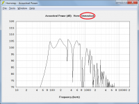
2. Masked / unmasked settings are not applicable to paraflex horns and are no longer shown in the chart captions of those systems.
Attachments 1 (before) and 2 (after) refer.
3. A number of other "loose ends" have now also been tidied up.
Kind regards,
David
Hi Everyone,
CHANGE
Paraflex horn designs exported from BOXPLAN can now be imported directly into the loudspeaker wizard.
BUG FIXES
1. The bugs reported by Brian in Post #11872 and Ty in Post #11878 have now been fixed.
2. Masked / unmasked settings are not applicable to paraflex horns and are no longer shown in the chart captions of those systems.
Attachments 1 (before) and 2 (after) refer.
3. A number of other "loose ends" have now also been tidied up.
Kind regards,
David
Attachments

- Home
- Loudspeakers
- Subwoofers
- Hornresp