Is there an easy way to adjust the scaling of the graphs? The automatic scaling is great, but if I'm visually comparing graphs from 2 or more different designs, it would help if they were using the same axes.
Is there an easy way to adjust the scaling of the graphs?
Hi SamAnytime,
Sorry, too much work. It would complicate things enormously. It's not going to happen 🙂.
The chart data for multiple designs could perhaps be exported as .csv files, and plotted on the one chart in Excel for comparison purposes.
Kind regards,
David
If I'm using a phase plug, am I right in assuming that
1. the phase plug is modeled in Hornresp as the first segment.
2. the sum of the areas of the entry ports of the phase plug is going to be the new throat area in Hornresp
and
3. the sum of the areas of the exit ports of the phase plug is going to be the new mouth of the first segment?
Also, where is the throat chamber in this scenario?
While we're on the subject of phase plugs, if the phase plug entry side is convex, thus occupying some of the free space in front of the driver cone, how does that affect our driver model?
It is up to the designer to decide how best to specify a phase plug in Hornresp. The first segment can certainly be used, but alternatively the throat adaptor component could be employed if all four segments were required for the actual horn.
Assuming that segment 1 is used, then S1 will be the sum of the phase plug entry ports and S2 will be the sum of the phase plug exit ports. A throat chamber could be specified to take into account the air volume between the driver diaphragm and the phase plug. If the phase plug entry side is convex, then the throat chamber volume would be reduced accordingly.
Assuming that segment 1 is used, then S1 will be the sum of the phase plug entry ports and S2 will be the sum of the phase plug exit ports. A throat chamber could be specified to take into account the air volume between the driver diaphragm and the phase plug. If the phase plug entry side is convex, then the throat chamber volume would be reduced accordingly.
Thanks, David. You're such an invaluable resource - and with apparently inexhaustible patience. Best wishes forever.
Hornresp Update 5050-200102
Hi Everyone,
CHANGE
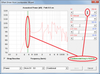
The loudspeaker wizard fundamental resonance frequency value can now be continuously displayed while adjusting the physical dimensions of a loudspeaker system, without the need to constantly move the mouse pointer over the chart green vertical marker line to re-show the value. Attachment 1 refers.
This change was requested by Giri in Post #10312.
BUG FIX
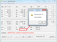
If Tal was temporarily set to a blank field in other than a direct radiator record, a fatal run-time error would be generated if the mouse pointer was moved over the Fr label or Fr input text box. Attachment 2 refers.
This bug has now been fixed. It was inadvertently introduced in update 5050-191206 when the feature allowing absorbent filling material to be specified in the throat port tube of a ME record, was added.
Kind regards,
David
Hi Everyone,
CHANGE
The loudspeaker wizard fundamental resonance frequency value can now be continuously displayed while adjusting the physical dimensions of a loudspeaker system, without the need to constantly move the mouse pointer over the chart green vertical marker line to re-show the value. Attachment 1 refers.
This change was requested by Giri in Post #10312.
BUG FIX
If Tal was temporarily set to a blank field in other than a direct radiator record, a fatal run-time error would be generated if the mouse pointer was moved over the Fr label or Fr input text box. Attachment 2 refers.
This bug has now been fixed. It was inadvertently introduced in update 5050-191206 when the feature allowing absorbent filling material to be specified in the throat port tube of a ME record, was added.
Kind regards,
David
Attachments
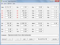
Is it possible to obtain the equivalent circuit for a design I've made in Hornresp? For a simple design perhaps, if the really complicated designs are hard to dump? I might have more success trying to optimise in the electrical domain.
Is it possible to obtain the equivalent circuit for a design I've made in Hornresp?
Only if you draw it yourself 🙂.
The amount of work required to make Hornresp capable of generating a graphical representation of the equivalent circuit used for a particular design simulation would be just too much. The 'virtual equivalent circuit' used internally by Hornresp probably wouldn't be of much use to you anyway, in that everything is converted into the acoustical rather than the electrical domain, and pressures and volume velocities rather than voltages and currents are used in the calculations.
Thanks David.
This is a useful addition to the information available.
How bad is the baking over where you are. Pretty hot all around Oz.
This is a useful addition to the information available.
How bad is the baking over where you are. Pretty hot all around Oz.
How bad is the baking over where you are. Pretty hot all around Oz.
Hi Mark,
Locally, we have had the hottest start to Summer on record, with several days above 40 deg C in December, the highest being 42 deg C (108 deg F) on the 15th. Some country towns have reached 50 deg C (122 deg F). Thankfully no bush fires near where I live. I guess you would have seen some of them on TV though - unbelievably bad. The firefighters, most of them volunteers, are true heroes.
Kind regards,
David
Let's leave things as they are for the moment, with the original driver parameters being kept.
Hi Brian,
Just letting you know that after thinking about it some more, I have decided to include the feature as an option in the next update 🙂.
It will work as follows:
If the Ctrl key is held down while pressing the F6 function key or clicking the Import command button to import a modified design directly into the loudspeaker wizard, the BOXPLAN worksheet driver parameter values will not be included in the imported data - the values used in the wizard will remain unchanged.
Kind regards,
David
1. After using the Max SPL tool, the graphs are often clipped to the limits set in the tool. This makes it difficult to see the effects of changes that you are making to try to rectify the problem, as the effects of the changes are not being shown. I have to turn off the limit set in the tool, do my adjustments, and then turn the limit back on to see how successful my changes have been.
Is it too much work to change this so that the limits (especially displacement) are shown by straight lines, and the portion of the graph that crosses the limit still be drawn, but shown in a different colour to indicate that it is illegal and needs to be fixed? This will make it easier to work towards the proper solution, as effects of a change will be visible.
E.g. if there is a peak in the displacement graph that is exceeding the limit that has been set, one of the ways to fix it is to decrease the volume of the rear chamber. If I decrease it a little bit, I can't see the result as the graph is still clipped. If it were not clipped, I could see whether I'm moving in the right direction, and whether I need to reduce it a little bit more.
2. In the Loudspeaker Wizard, is there a 'fine control' for the sliders? E.g. if a click advances the Vrc slider by 0.1 liters, a click with the SHIFT key held down should advance it by 0.01.
3. Are there typical workflow tutorials to explain how to use Hornresp? Even the screen you see when you first launch Hornresp after installation seems very daunting at first as everything is greyed out. The help file has everything, but a guided example would go a long way to making this user friendly. There are several such tutorials on the internet, but they are very rudimentary and don't explain the usage of the many tools and additional graphs.
Hi SamAnytime,
Rather than using the Maximum SPL tool in this case, simply make your adjustments in the loudspeaker wizard while viewing the diaphragm displacement chart. If Xmax is 5 mm (for example) then the objective would be to keep the displacement below that value over the frequency range of interest. You can observe the effect of your adjustments as you go.
While not necessarily obvious to the user, the algorithms controlling the operation of the sliders are already extremely complex, and introducing another level of (adjustable) precision is simply out of the question at this stage.
If you wish to see what the results are doing between say 50.10 and 50.20 litres (for example at 50.13 litres) then when the Vrc slider has the focus, simply key in 50.13 and press Enter. The attachment refers.
Not that I am aware of. There are now so many features in Hornresp (most added at the request of users) that it would be very difficult to adequately address them all in the way that you propose. The Input Wizard was added in an attempt to make it a bit simpler to get started, but realistically, there is no quick and easy way to learn how to fully exploit all the tools now available in Hornresp.
Kind regards,
David
Is it too much work to change this so that the limits (especially displacement) are shown by straight lines, and the portion of the graph that crosses the limit still be drawn, but shown in a different colour to indicate that it is illegal and needs to be fixed?
Rather than using the Maximum SPL tool in this case, simply make your adjustments in the loudspeaker wizard while viewing the diaphragm displacement chart. If Xmax is 5 mm (for example) then the objective would be to keep the displacement below that value over the frequency range of interest. You can observe the effect of your adjustments as you go.
In the Loudspeaker Wizard, is there a 'fine control' for the sliders? E.g. if a click advances the Vrc slider by 0.1 liters, a click with the SHIFT key held down should advance it by 0.01.
While not necessarily obvious to the user, the algorithms controlling the operation of the sliders are already extremely complex, and introducing another level of (adjustable) precision is simply out of the question at this stage.
If you wish to see what the results are doing between say 50.10 and 50.20 litres (for example at 50.13 litres) then when the Vrc slider has the focus, simply key in 50.13 and press Enter. The attachment refers.
Are there typical workflow tutorials to explain how to use Hornresp?
Not that I am aware of. There are now so many features in Hornresp (most added at the request of users) that it would be very difficult to adequately address them all in the way that you propose. The Input Wizard was added in an attempt to make it a bit simpler to get started, but realistically, there is no quick and easy way to learn how to fully exploit all the tools now available in Hornresp.
Kind regards,
David
Attachments
Ported loudspeaker box modelling
David,
I'm using your programme but unsure about how to add a vent port in the Loudspeaker wizard. This is what I did:
Loaded driver details
Selected rear lined driver
Added Lrc, Vrc values I calculated/guessed
But could not add the port length and diameter to the module.Can you pls help?
Thanks
Atiq
Attachments


Hi Atiq,
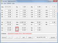
The easiest way to specify a bass reflex type loudspeaker is to use the Input Wizard (accessed from under the Help menu) to generate a representative example, and to then change the input parameter values to suit the specific design. Attachment 1 refers.
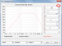
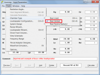
In your case, because you are already nearly there, simply double-click on the Fr label on the main input parameters screen when the record is in edit mode, to change Fr and Tal to Ap and Lpt. Alternatively you could select the Rear Vented rather than the Rear Lined option from the Chamber Type menu, as shown in Attachment 2. Use the 'resonances masked' option (selected from the Tools > Options menu) if you wish to suppress the enclosure resonances.
Ap is the port cross-sectional area and Lpt is the port tube length.
With regard to the Kaspersky problem, I am not familiar with how the software operates so I cannot help you much there. Norton sometimes generates a false positive and quarantines Setup.exe when the file is first downloaded, but the user is able to confirm that the file is safe, and the quarantined file is then automatically restored. I would have thought that Kaspersky should behave in a similar way. Perhaps someone who uses Kaspersky could comment further...
Kind regards,
David
The easiest way to specify a bass reflex type loudspeaker is to use the Input Wizard (accessed from under the Help menu) to generate a representative example, and to then change the input parameter values to suit the specific design. Attachment 1 refers.
In your case, because you are already nearly there, simply double-click on the Fr label on the main input parameters screen when the record is in edit mode, to change Fr and Tal to Ap and Lpt. Alternatively you could select the Rear Vented rather than the Rear Lined option from the Chamber Type menu, as shown in Attachment 2. Use the 'resonances masked' option (selected from the Tools > Options menu) if you wish to suppress the enclosure resonances.
Ap is the port cross-sectional area and Lpt is the port tube length.
With regard to the Kaspersky problem, I am not familiar with how the software operates so I cannot help you much there. Norton sometimes generates a false positive and quarantines Setup.exe when the file is first downloaded, but the user is able to confirm that the file is safe, and the quarantined file is then automatically restored. I would have thought that Kaspersky should behave in a similar way. Perhaps someone who uses Kaspersky could comment further...
Kind regards,
David
Attachments
Masking vs unmasking
David,
What are the differences between resonance masking and unmasking? Unmasking is more realistic? Is it possible to add insulation using the wizard for a ported speaker box ?
I could not bypass Kaspersky even though I changed its settings asking to ignore the detection. I used Wayback to get July version of Hornresp. It works with Kaspersky but time delay and phase margin are unavailable.
Many thanks for your kind reply.
Atiq
Parallel drivers
David,
I'm paralleling 2 woofers in one speaker box. Is it the right way of doing this?
1. Fill out the driver wizard for a single driver
2. Choose speaker configuration: select 2 driver in series/parallel
3. Run the sim
Question:
Do I need to change Le/Ze values for 2 drivers? or Hornresp will auto calculate based upon speaker config chosen?
How about the input power 'Eg' values? Do I need to double the impedance and power,for example, for 2 series connected drivers?
Thanks for your patience.
Atiq
Hi Everyone,
CHANGE
The loudspeaker wizard fundamental resonance frequency value can now be continuously displayed while adjusting the physical dimensions of a loudspeaker system, without the need to constantly move the mouse pointer over the chart green vertical marker line to re-show the value. Attachment 1 refers.
This change was requested by Giri in Post #10312.
Kind regards,
David
Thank you so much, David. It's such a joy to use.
Hi Atiq,
When the 'resonances masked' option is selected, the enclosure chamber is modelled as a simple acoustic compliance (this is the model used in most standard "box" type simulation programs). When the 'resonances not masked' option is selected this simplifying assumption is not made, and a more rigorous model is used that shows the higher frequency chamber resonances caused by reflections from the back of the cabinet (opposite to the rear side of the driver).
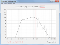
If the actual built loudspeaker is going to have a lined chamber then the 'resonances masked' option can be confidently used for the simulations. If the actual built loudspeaker is going to have an unlined chamber then it is perhaps better to use the 'resonances not masked' option for the simulations. At the lower frequencies there is effectively no difference between the two models. In Attachment 1 the dark trace shows the response of a simple bass-reflex system with resonances masked and the light trace shows the response of the same system with resonances not masked. The traces are effectively identical below about 800Hz.
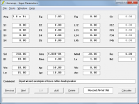
It is not possible to add acoustical lining, but by specifying the system in a different way, it is possible to add absorbent filling material. Attachment 2 shows an example of a standard bass-reflex system and Attachment 3 shows the same system specified so that filling material can be added using the loudspeaker wizard. A 2.45 cm extension to the port tube is required in this case though, to account for the internal end correction (which is automatically included when the port tube is specified using Ap and Lpt).
Yes. Alternatively, you could just double-click on the disabled Nd text box in edit mode to open the Loudspeaker Configuration tool. You want the Nd text box to show 2P, which indicates two drivers connected in parallel.
No, Hornresp automatically changes the driver parameter values as necessary, internally, to account for multiple drivers.
This is a decision for you to make. Hornresp assumes that the amplifier delivers a constant voltage Eg at all frequencies, regardless of the load impedance.
Kind regards,
David
What are the differences between resonance masking and unmasking?
When the 'resonances masked' option is selected, the enclosure chamber is modelled as a simple acoustic compliance (this is the model used in most standard "box" type simulation programs). When the 'resonances not masked' option is selected this simplifying assumption is not made, and a more rigorous model is used that shows the higher frequency chamber resonances caused by reflections from the back of the cabinet (opposite to the rear side of the driver).
Unmasking is more realistic?
If the actual built loudspeaker is going to have a lined chamber then the 'resonances masked' option can be confidently used for the simulations. If the actual built loudspeaker is going to have an unlined chamber then it is perhaps better to use the 'resonances not masked' option for the simulations. At the lower frequencies there is effectively no difference between the two models. In Attachment 1 the dark trace shows the response of a simple bass-reflex system with resonances masked and the light trace shows the response of the same system with resonances not masked. The traces are effectively identical below about 800Hz.
Is it possible to add insulation using the wizard for a ported speaker box?
It is not possible to add acoustical lining, but by specifying the system in a different way, it is possible to add absorbent filling material. Attachment 2 shows an example of a standard bass-reflex system and Attachment 3 shows the same system specified so that filling material can be added using the loudspeaker wizard. A 2.45 cm extension to the port tube is required in this case though, to account for the internal end correction (which is automatically included when the port tube is specified using Ap and Lpt).
I'm paralleling 2 woofers in one speaker box. Is it the right way of doing this?
Yes. Alternatively, you could just double-click on the disabled Nd text box in edit mode to open the Loudspeaker Configuration tool. You want the Nd text box to show 2P, which indicates two drivers connected in parallel.
Do I need to change Le/Ze values for 2 drivers?
No, Hornresp automatically changes the driver parameter values as necessary, internally, to account for multiple drivers.
How about the input power 'Eg' values? Do I need to double the impedance and power, for example, for 2 series connected drivers?
This is a decision for you to make. Hornresp assumes that the amplifier delivers a constant voltage Eg at all frequencies, regardless of the load impedance.
Kind regards,
David
Attachments
- Home
- Loudspeakers
- Subwoofers
- Hornresp