Hi Freddy,
The model I suggested is the closest that you can get using Hornresp, but it is by no means perfect 🙂. Hopefully the power response prediction should be reasonable though, provided that the Output 2 result is used.
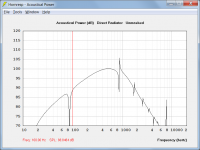
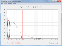
It appears that the notch you are seeing is due to the effect of the very small hole in the second chamber. Notice how if you increase S5 to 1.00 sq cm for example, the notch disappears. I have no experience with dual chamber designs, but presumably the notch would not be present in a practical system, if the second chamber was completely sealed.
For a serious analysis it would be safer to use AkAbak, but I gained the impression that you were looking for an indicative result only, which is why I was prepared to provide the suggested Hornresp "compromise" model 🙂.
Kind regards,
David
Hi Freddy,
Further to my message above, my curiosity got the better of me 🙂.
I temporarily jury-rigged Hornresp so that the second chamber was completely sealed.
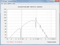
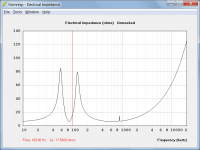
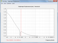
Attachments 1 to 3 show the results obtained using a completely sealed second chamber.
Attachments 4 to 6 show the results obtained using the originally suggested "compromise" model.
As anticipated, the power responses are similar, and the notch in the diaphragm displacement disappears when the second chamber is completely sealed.
The electrical impedance results are also much the same.
Kind regards,
David
Attachments

Do you want to say that this resonance camera have connection to the main box? I don't see that.@ Orion33
Helmholtz = Reflex It's the same thing, with a different name 😉
But Helmholtz resonator is not bass-reflex system. See please picture
Hi Orion33,
I see what you mean - the design shown is obviously a bit different to a standard bass-reflex / Helmholtz resonator setup.
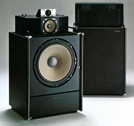
It is not clear to me from the cut-away photo exactly how the system is configured, but perhaps the attachments below will give you some ideas to work with. I would be very surprised indeed if the two chambers were not interconnected in some way.
Kind regards,
David
Attachments


Thank you, David. Are you right with first section? Input square is very small.
Sorry, I undestood, main box is throat chamber.
Sorry, I undestood, main box is throat chamber.
Last edited:
Hi Orion33,
I see what you mean - the design shown is obviously a bit different to a standard bass-reflex / Helmholtz resonator setup.
It is not clear to me from the cut-away photo exactly how the system is configured, but perhaps the attachments below will give you some ideas to work with. I would be very surprised indeed if the two chambers were not interconnected in some way.
Kind regards,
David
The two chambers are indeed connected. This is a type of bandpass enclosure.
the design shown is obviously a bit different to a standard bass-reflex / Helmholtz resonator setup.
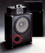
The reason why I originally thought that the Technics SB-7000 was a conventional bass-reflex design was because I was looking at the attached photo, which clearly shows a port in the front baffle 🙂.
Attachments
Last edited:
I temporarily jury-rigged Hornresp so that the second chamber was completely sealed.
I have started looking into the possibility of the user being able to specify a closed-mouth horn, which would mean that it would not be necessary to use a "compromised" model.
I don't know wherefrom this picture is.The reason why I originally thought that the Technics SB-7000 was a conventional bass-reflex design was because I was looking at the attached photo, which clearly shows a port in the front baffle 🙂.
It from japanese audio-heritage:
David, another question.
Is ot bossible to calculate impulse response with filling? This option is avaiable on loudspeaker wizard only but it haven't impulse image.
Is ot bossible to calculate impulse response with filling? This option is avaiable on loudspeaker wizard only but it haven't impulse image.
Indeed, a spreadsheet was promised nearly 2 months ago 😱Would it be possible to implement your suggested optional approach using an Excel spreadsheet, perhaps?
Hornresp #8272
Have finally gotten back on task cleaning it up, and adding some functionality to help deal with less than optimal data. Should have something available for Beta testing by this time next week. In the mean time, as mentioned a few times, you can use REW or ARTA/LIMP. If you have a text data file from another impedance measurement program, you can import into REW. You only need the free-air measurement to calculate the semi-inductance parameters.
Inductance Cancellation Techniques
So, I may be asking too much of the wavefront simulator, but do you think it would be possible to have a dampening material like cloth or foam? I tried using a spray of dots but it only resulted in spontaneous biogenesis of ant colonies.
To an extent, you can simulate the effect of foam with power tapering. Because foam attenuates sound just as power tapering attenuates sound.
You only need the free-air measurement to calculate the semi-inductance parameters.
Now that is some good news. I'm tempted to review a few of my builds to see if switching to the semi-inductance model provides a closer fit to the measured results.
I don't know wherefrom this picture is.
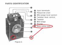
The attached image was copied from the Operating Instructions manual for the loudspeaker.
Attachments
Is ot bossible to calculate impulse response with filling?
Hi Orion33,
No, Hornresp does not allow you to do this.
Kind regards,
David
Thank you for this info. It was 7000A, perhaps, second edition of first 7000.The attached image was copied from the Operating Instructions manual for the loudspeaker.
Thank you for this info. It was 7000A, perhaps, second edition of first 7000.
It is interesting that Panasonic / Technics changed to a conventional bass-reflex system in the later model.
Perhaps they found that it performed better than the system used in the original version.
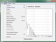
Can you help me function Compare previous the program hornrasp Compare graph 4-5 graph simultaneously.
Hi Piyapong38,
I am not sure what you mean by "Compare graph 4-5 graph simultaneously". 'Compare Previous' allows the user to compare current results against previously calculated results. 'Compare Captured' allows the user to compare current results against previously captured results. In each case only two sets of results are compared. Further details can be found in the 'Compare' section of the Hornresp Help file.
Kind regards,
David
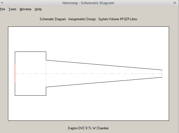
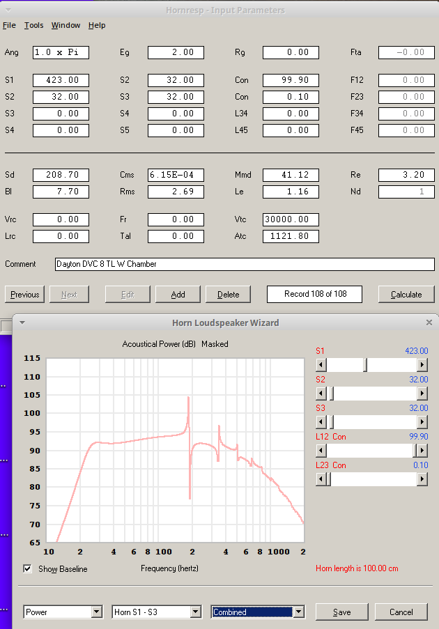
TL with back chamber
A few questions. For a project I am looking to make a TL sub with a back chamber that feeds the line.
1. Is this the way to model it?
2. Is it a feasible approach?
3. Does the entry to the line need to be directly behind and concentric to the driver or could it be a slot at the bottom rear of the chamber?
4. Has anyone done such a thing?
Attachments


- Home
- Loudspeakers
- Subwoofers
- Hornresp