Hi Brian,
To avoid the previously mentioned potential slider "lock-up" problems, it may be necessary to limit the diaphragm displacement algorithm to only looking for resonances below 100Hz. Would this be sufficient for your purposes?
Yup, that would be fine by me.
Making Hornresp easier to use?
How could you?
Everytime you make it more chimp proof they invent better chimps.
It's a never ending cycle.
How could you?
Everytime you make it more chimp proof they invent better chimps.
It's a never ending cycle.
Yup, that would be fine by me.
Hi Brian,
The good news is that I have managed to come up with a reasonably efficient way of finding the lowest resonance frequency, which means that it should be possible to remove the 100Hz limit and use the default chart maximum of 2000Hz instead, so that the frequency range tested is no longer an issue 🙂.
I ended up identifying the resonance frequency from the electrical impedance rather than from diaphragm displacement. The results are significantly more accurate and consistent when impedance is used.
Hopefully the lowest resonance frequency feature will be included in the next release.
Kind regards,
David
I ended up identifying the resonance frequency from the electrical impedance rather than from diaphragm displacement. The results are significantly more accurate and consistent when impedance is used.
Don't the resonant frequency(s) correspond exactly to the dips in excursion?
Don't the resonant frequency(s) correspond exactly to the dips in excursion?
Resonance is usually the highest peak in the electrical impedance.
When talking about portet enclosures (bassreflex), the impedance resonance peaks don´t correspond to the resonance frequency of the port. Excursion Minimum is close, but not exactly the same. I´d have to look up the formula (Vance Dickasson has it in his measurement book) how to calculate port-resonance from the imp-chart. But I guess David already has something figured out ?
When talking about portet enclosures (bassreflex), the impedance resonance peaks don´t correspond to the resonance frequency of the port. Excursion Minimum is close, but not exactly the same. I´d have to look up the formula (Vance Dickasson has it in his measurement book) how to calculate port-resonance from the imp-chart. But I guess David already has something figured out ?
Yes. That is true.
It is the same situation with a bandpass.
Impedance minimum.
It''s those differences that make an easy solution a little bit more difficult to achieve.
Yes, it makes it tricky 🙂
As far as I recall, Imp. Minimum is close, but not exactly tuning freuquency. I´d have to look up the formula, don´t have it in my head and the book is not at hand..
As far as I recall, Imp. Minimum is close, but not exactly tuning freuquency. I´d have to look up the formula, don´t have it in my head and the book is not at hand..
In a few situations it is a combination of phase angle at the zero crossing point and the impedance at that point.
But I to have to look if there are exceptions to this.
So many things to keep in mind that this work never ceases to impress upon me what bits of knowledge I am missing. Sometimes because of lack of use. Sometimes because of not knowing.
It keeps me always wanting to learn more and ask and seek the answer to different questions.
Never a unhappy moment in this business.
Hi David
Is the port dimensions such that I have to divide them? like the ap1 is 12 cm wide and has 113 cm2 total for 4 ports, (two each woofer).
It is for to be shure, because I think I have the answer already.
when divide them horn is more happy keeping material on him.
thanks
Is the port dimensions such that I have to divide them? like the ap1 is 12 cm wide and has 113 cm2 total for 4 ports, (two each woofer).
It is for to be shure, because I think I have the answer already.
when divide them horn is more happy keeping material on him.
thanks
Attachments
Last edited:
Hi Everyone,
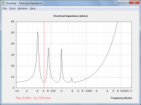
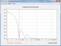
Before I go any further and just so that I understand exactly what is required, given the attached impedance and displacement charts, can we reach a consensus on what is considered to be the 'lowest resonance frequency' of the sample system?
It would seem from recent posts that we have three options to choose from:
1. First impedance peak - 41.20 hertz.
2. First impedance minimum after the first peak - 61.49 hertz.
3. First displacement dip - 62.38 hertz.
(The frequency of first impedance minimum after the first peak is usually very close to the frequency of the first displacement dip).
What is the 'lowest resonance frequency' of this system?
Kind regards,
David
Attachments

Is the port dimensions such that I have to divide them? like the ap1 is 12 cm wide and has 113 cm2 total for 4 ports, (two each woofer).
Hi Kees,
Hornresp has no way of knowing how many ports there are, so you need to specify the total area.
For the example you give, if Ap is shown in Hornresp as 113 cm2 and you intend having four ports, then you are assuming that each of those ports has a cross-sectional area of 28.25 cm2 and a diameter of 6 cm.
Kind regards,
David
Definitely not #1. Resonances happen between impedance peaks. Excursion is already way out of control at the lowest impedance peak so there's no point at all in marking the lowest impedance peak.
#2 might be more technically correct than #3 but it hardly makes any difference, it's less than 1 hz apart. if there's a question of which is easier to implement I'd go for the easier option between #2 and #3.
#2 might be more technically correct than #3 but it hardly makes any difference, it's less than 1 hz apart. if there's a question of which is easier to implement I'd go for the easier option between #2 and #3.
Definitely #3 - it is the only one which is directly acoustically related to the whole SPL output.
Theoretically, it's the mean between the two peaks IIRC, but don't know how HR calculates the peaks in #2 and dip in #3, which would theoretically be at the same frequency, so no clue why there's a slight offset. Regardless, I use #3 as it's plenty close enough.
GM
GM
#2 might be more technically correct than #3 but it hardly makes any difference, it's less than 1 hz apart. if there's a question of which is easier to implement I'd go for the easier option between #2 and #3.
Agreed.
I'm going to look up a few sources and then comment.
Something tells me from foggy memories in the far reaches that there are exceptions depending on the enclosure type.
Something tells me from foggy memories in the far reaches that there are exceptions depending on the enclosure type.
Definitely #3 - it is the only one which is directly acoustically related to the whole SPL output.
Agreed.
Loudspeaker Driver Design
While dated, the following book, published by the ASA, may help those that have interest in the subject.
"Electroacoustics -The Analysis of Transduction and Its Historical Background"
Author: Frederick V. Hunt
Electroacoustics
Note that inductance is a function of the total number of turns in the voice coil, while motor strength (bl product) is a function of the length of voice coil wire effectively immersed in the magnetic gap. Thus, a smaller diameter voice coil typically will have a much higher inductance than that of a voice coil of larger diameter where the dcrs and bl products of each driver are comparable.
WHG
Last edited:
- Home
- Loudspeakers
- Subwoofers
- Hornresp