"EQ isn't going to fix that high-Q null at 11K in the Pyle Econowave."
I wonder if foam would help.
I wonder if foam would help.
catapult said:Brandon said he's going to do the JBL and the Pyle again with a BMS 4540 when Thomas brings one over. That said, I don't think it's going to fix everything. I think Earl's 1/3 octave curves are hiding a lot of sins that Brandon's unsmoothed curves reveal in all their glory. It's that pesky old physics thing and what happens when you have a sharp edge at the mouth and a throat that's quite a bit smaller than 1".
What has a throat that's smaller than 1"?
We have a discrepancy:
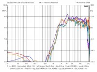
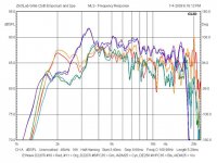
ADM25 = Selenium, PC35 = P-Audio throat adapters.
Only the thread-on D220Ti shows a shallow notch @ 10.5 kHz with no smoothing.
With throat adapters, D220Ti bolt-on shows similarly high-Q notches at lower frequencies.
DE250 shows no notches.
These are freestanding; I'll see what happens on a baffle....
Attachments
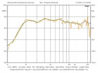
The worst of them, orange, mounted 1" down on a 17" x 21" baffle, yellow, then smoothed 1/3 octave, and the familiar EconoWave response curve appears.
I've got to wonder if there isn't some heretofore unrecognized anomaly in the Pyle PH612 metal insert throat. I'll have to order a pair to see, apparently....
I've got to wonder if there isn't some heretofore unrecognized anomaly in the Pyle PH612 metal insert throat. I'll have to order a pair to see, apparently....
Attachments
gedlee said:Looks a little like the phase between the woofer and tweeter might be off a little bit as the null should be a little further "up". The resistor in series with the large LP cap has a big effect on this phase and will shift this null up and down with almost no change in any other aspect. I'm just finishing a couple pair of Nathans that I'll test this week and see if they show the same thing and what I can do to improve it. I'll let you know.
Hello Earl,
what did you find out?
Best, Markus
ZilchLab said:I've got to wonder if there isn't some heretofore unrecognized anomaly in the Pyle PH612 metal insert throat.
It might be nice to see the DT220 on the Selenium HL14-25 horn, as that is what they always publish for datasheets. They are only about $6 each, but P.E. is out of stock for the moment.
panomaniac said:
It might be nice to see the DT220 on the Selenium HL14-25 horn, as that is what they always publish for datasheets. They are only about $6 each, but P.E. is out of stock for the moment.
I have both the Pyles and the P-Audio throat adapters Augerpro is using on order, and will verify his findings upon arrival.
That Selenium horn is an exponential, not CD, alas, as I recall....
 LEV and spacial discussion split off here
http://www.diyaudio.com/forums/showthread.php?postid=1865787#post1865787
Iain McNeill said:
http://www.diyaudio.com/forums/showthread.php?postid=1865787#post1865787
Nice!
Graci. 🙂
Iain McNeill said:
http://www.diyaudio.com/forums/showthread.php?postid=1865787#post1865787
Cool thread, and it's got 60K+ hits already! 😛
What are your educated opinions on why some horn speakers tend to sound better when driven by much more powerful amps than one would expect they need?
Thanks for any insights
Thanks for any insights
Horns have better sensitivity, and if designed correctly, have a more uniform wave front. This makes it more revealing of problems that may occur for whatever reason.
olduvai said:What are your educated opinions on why some horn speakers tend to sound better when driven by much more powerful amps than one would expect they need?
Thanks for any insights
A big woofer in a horn, even if high sensitivity, it needs some power
Big woofers, even if relatively light, still weighs a bit more than lightweight widebaders
This would be my most minimally educated explanation. First, without further explanation of the specific scenario, this is all conjecture, but would be my best guess as to what is being described.
Speaking solely of the woofer part of a high sensitivity horn or waveguide based system, the woofers can still draw a great deal of power. Depending on the phase angle and impedance of the drivers, it's possible to have a speaker drawing a great deal of current from the amplifier, and thus, beefier solid state amps tend to be better suited to such situations. Many modern "pro" drivers have enough excursion ability to fully utilize their power handling ability before exceeding xmax (within certain applications), and many also have lower sensitivity than I'm used to seeing on such drivers, causing them to really demand more power for a given output. That being said, these high efficiency speakers, such as the Gedlee Abbey's that I own, are capable of such ridiculous output levels, as to never be exceeded under normal situations, and I would guess that no more than 100-200 watts is needed to reach painfully and dangerously loud levels.
Speaking in terms of the horn/waveguide and compression driver, these are typically fairly sensitive as compared to the Midbass drivers, and a fairly substantial amount of padding is frequently used to deal with that. This means that a great deal of power is being wasted as heat. The impedance of these drivers tends to be higher than lower range drivers, and they tend not to be as current hungry, meaning they really shouldn't need any beefier of an amp. I've not studied the impedance vs phase angle of enough compression drivers to make much of a guess, but I can't imagine ever needing a huge amp here. Which isn't to say that certain compression drivers, regardless of efficiency level, used in certain ways, wouldn't utilize quite a bit of power. For instance, the lower it's used, the more current hungry I would imagine it would become. Additionally, if asked to play at fairly loud levels, I could easily see needing more power (obviously), and it is perfectly feasible that a small tube amp would be unable to deliver that power (or even a small solid state amp for that matter).
If we are talking about a horn speaker specifically, and not the midbass driver, I would look at it's impedance/phase angle carefully and make sure there is something about the crossover design causing a bad combination and thus greater current needs. It's possible the setup is drawing unnecessary amounts of current and just dumping it as heat, and a simple redesign of the crossover would help a lot.
Polar measurements (with video showing off-axis nulls)
Recently I started a little project, and like all of my loudspeakers, I designed it to provide uniform coverage over a 90°x40° pattern. As most of you know, the loudspeaker has to be capable of providing good response at various places, which is not an altogether easy task. To test its performance, you have to move the microphone and measure off-axis as well as straight in front of the speaker.
I have found it isn't too hard to obtain uniform horizontal coverage. That's largely a function of the horn used, which must provide constant directivity along the horizontal plane. The only thing in addition to that are the crossover points, which must be done where the sound sources have matching coverage. In the case of a direct radiating midwoofer and a horn tweeter, the frequency where they match is determined by the size of the woofer and the angular coverage of the tweeter. When using a 90° horn, the woofer matches directivity at the frequency where wavelength is approximately equal to diameter. There is a pretty wide margin here though, I've found that as long as you're within about a third octave, the pattern is still very uniform.
It is harder to get the vertical pattern right. This is because of path length distances between the listener and the woofer and tweeter. Movement along the vertical axis causes the path length differences to change. Once you near 1/2 wavelength, nulls form.
I did a little video that shows these nulls, hoping that would give a clearer picture of what to expect. Some people are already very familiar with this, so it's not news to them. But many people struggle with the concept of vertical nulls, what they are, and how to find them. Hopefully, this video will be helpful, because it shows one of the things I do during development, and it also shows a speaker that I think is a good example as far as vertical coverage is concerned. It has a tall forward lobe that is useful at most any listening distance.
When I move the microphone to the bottom edge of the speaker, you'll see a notch form in the response curve. That is the lower null. Later, I move the microphone to a position beyond the top edge of the speaker. Watch the response curve as I move the microphone, you'll see it remains flat until I reach the upper null, where a dip again forms.
You might also notice that when I moved the microphone to show the lower null, I moved it just a smidge too far - just past the deepest part of the null. But you can still clearly see the upper and lower nulls, and the smoothness of response in between. Pay attention to the response curve as I move the microphone, you'll see it stays nice and smooth all the way between nulls, over a wide vertical range.
Recently I started a little project, and like all of my loudspeakers, I designed it to provide uniform coverage over a 90°x40° pattern. As most of you know, the loudspeaker has to be capable of providing good response at various places, which is not an altogether easy task. To test its performance, you have to move the microphone and measure off-axis as well as straight in front of the speaker.
- three Pi upgrade (using the TD12S woofer)
I have found it isn't too hard to obtain uniform horizontal coverage. That's largely a function of the horn used, which must provide constant directivity along the horizontal plane. The only thing in addition to that are the crossover points, which must be done where the sound sources have matching coverage. In the case of a direct radiating midwoofer and a horn tweeter, the frequency where they match is determined by the size of the woofer and the angular coverage of the tweeter. When using a 90° horn, the woofer matches directivity at the frequency where wavelength is approximately equal to diameter. There is a pretty wide margin here though, I've found that as long as you're within about a third octave, the pattern is still very uniform.
It is harder to get the vertical pattern right. This is because of path length distances between the listener and the woofer and tweeter. Movement along the vertical axis causes the path length differences to change. Once you near 1/2 wavelength, nulls form.
I did a little video that shows these nulls, hoping that would give a clearer picture of what to expect. Some people are already very familiar with this, so it's not news to them. But many people struggle with the concept of vertical nulls, what they are, and how to find them. Hopefully, this video will be helpful, because it shows one of the things I do during development, and it also shows a speaker that I think is a good example as far as vertical coverage is concerned. It has a tall forward lobe that is useful at most any listening distance.
- Vertical Nulls (video)
When I move the microphone to the bottom edge of the speaker, you'll see a notch form in the response curve. That is the lower null. Later, I move the microphone to a position beyond the top edge of the speaker. Watch the response curve as I move the microphone, you'll see it remains flat until I reach the upper null, where a dip again forms.
You might also notice that when I moved the microphone to show the lower null, I moved it just a smidge too far - just past the deepest part of the null. But you can still clearly see the upper and lower nulls, and the smoothness of response in between. Pay attention to the response curve as I move the microphone, you'll see it stays nice and smooth all the way between nulls, over a wide vertical range.
"Speaking in terms of the horn/waveguide and compression driver, these are typically fairly sensitive as compared to the Midbass drivers, and a fairly substantial amount of padding is frequently used to deal with that. This means that a great deal of power is being wasted as heat. "
Only in a relative sense, i.e. the padding relative to the CD - more padding = higher resistance = lower current/power draw.
Only in a relative sense, i.e. the padding relative to the CD - more padding = higher resistance = lower current/power draw.
Voltage divider in example speaker attenuating tweeter by 12db's and fed by 200 watts gives:
150 watts through series resistor
38 watts through the parallel resistor
12.6 watts as the speaker
That's 187.4 watts wasted as heat through the resistors.
150 watts through series resistor
38 watts through the parallel resistor
12.6 watts as the speaker
That's 187.4 watts wasted as heat through the resistors.
Wow, I was way off on that one.
Makes a good case for active XO I guess.
But I don't think it's as bad as it seems at first blush.
It would take 89 V to get that power into 40 ohms (assuming 8 ohm CD), which is a 1000 W into 8 ohms.
Si if the bass/mid is 8 ohms, less than 20% of the power is being lost in the padding.
Also, this would be a peak/intermittant dissipation rather than average, as this power would give >110 dB SPL.
well I was intentionally using an excessive case to make the point of what "could" happen. It would almost never see that kind of power, or anything even close to it. The reality of the situation is clearly far more complicated than what that simple example shows. Basically, we first made the assumption that we setup the voltage divider at the same impedance as the woofer. When I design speakers I don't typically do that since often amplifiers perform better with a rising impedance at higher frequencies.
Then there is the fact that the formula I used to calculate those numbers assumes a constant incoming amount of power, and given the dynamic nature of the signal and reactive nature of the load, we know that isn't even close to true.
The point was simply that, if you were pushing speakers hard and the amp was delivering very large amounts of power, it could lead to a situation where the tweeter was itself drawing a lot of power from the amplifier, and wasting much of it as heat.
Where I would say it doesn't make the case for active crossovers is simply that, as said, it's all more complicated than I made it out to be, and in reality, most of the time, the system would not be doing this. I suppose the inefficiency is always there, but it's typicall of much less concern than it would be in this example. Since resistors can handle such ridiculous loads for the very brief moments of those dynamic peaks, they are a much cheaper way of dealing with the padding issue than separate amps and crossovers.
I actually promote the use of a voltage divider and impedance correction done passively with tweeters since it helps give the amplifier a more stable and expected load, making the active crossovers then more effective. It also offers some minimal amounts of protection to the tweeter in the event of amplifier failure (a single capacitor adds that much more).
- Status
- Not open for further replies.
- Home
- Loudspeakers
- Multi-Way
- Horn vs. Waveguide