MJL21193 said:I do like the idea of a stand alone unit, dedicated to this rather than a computer and sound card. I generally use my "lab" computer to run Speaker Workshop, so I need to change the cables and settings and it become too much of a headache to run RMAA.
What would be the overall cost Glen?
Well yes, I can think of a few reasons why, say, someone with an amateur interest in mixing/recording/producing may prefer a 1U rack case over another PC for monitoring purposes.
This 21-band unit is more of a toy designed and built for the fun of it more than anything.
The 60 band 1/6 octave unit with the much more accurate and selective filters will be a far more serious instrument though.
Jan; The monster amps are progressing slowly. I'm juggling multiple projects.
Cheers,
Glen
G.Kleinschmidt said:[snip] I'm juggling multiple projects.
Cheers,
Glen
Sounds familiar...
Jan Didden
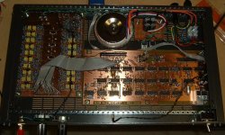
Got the thing up and running in a 1U-rack case today. Still have to etch in install the final version of the digital PCB though. The prototype board version in currently in situ, insulated from the chassis with a bit of cardboard 😀
Have not begun the write-up on the circuit operation yet, but the diagram attached below that I just put together in MS Paint, along with the schematics on my website, should explain everything............ 😕
Cheers,
Glen
An externally hosted image should be here but it was not working when we last tested it.
Have not begun the write-up on the circuit operation yet, but the diagram attached below that I just put together in MS Paint, along with the schematics on my website, should explain everything............ 😕
Cheers,
Glen
Attachments

janneman said:I just looked at EZGPIB the other day. I have a Neutrik RT-1M I'm trying to talk (and listen) to over the GPIB. Multitone audio analyzer, should be fun to get it going.
But I have some hardware problems, looks like IRQ conflicts. All that legacy stuff is far from PnP!
Jan Didden
Edit: Sorry for OT. I'll shut up now...
Hi Janneman!
How do you proceed with RT-1M?
BR,
Milan
 )
)
I've also updated my website with an 80% complete write up on how the thing works:
http://users.picknowl.com.au/~glenk/VGAASAMK1.HTM
Still have to add the powersupply and wiring schematics.
If I get the time this week I'm going to place an MOQ order for those 1/6 octave switched capacitor chips from MSI for the 60 band MKII analyser.
I'll update this thread with the initial evaluation results if anyone is interested.
Cheers,
Glen
Time to resurrect this thread as, with that VGA Spectrum analyser intermission out of the way, I have finally gotten back to the fancy digital sampling swept frequency spectrum analyser project that I outlined in this threads opening post. 
I have, however, scrapped all the previous design work and redesigned to a higher performance specification. As another project on the go I am essentially designing and building my own AP-functional audio analyser system, so I figured I might as well make a companion spectrum analyser of comparable sophistication. I intend to use this spectrum analyser primarily to examine the harmonic spectrum of the THD residual extracted by the audio analyser.
As originally intended, the spectrum analyser will still work as stand-alone unit, providing X/Y/(Z) outputs to drive and generate a display on a conventional analogue oscilloscope, but I have, however, redesigned the digital sampling recorder/motherboard with an RS232 / USB interface for computer control / display / storage as well (I have been looking for a good excuse to upgrade from MS Visual Basic to MS Visual C, and the graphical interface for this project will be a good excuse).
I have also radically revamped the design by increasing the display / recorder resolution (for the horizontal sweep as well as the vertical axis) to 12-bits. This has significantly increased the complexity of the unit.
Anyway, besides this (12-bit resolution and PC interface), the basic operation of this part of the analyser is the same as the previous version I described in post 27:
http://www.diyaudio.com/forums/showthread.php?postid=1495589#post1495589
For the new design I have scrapped the discrete low-resolution R/2R ladder DAC’s and replaced with high performance 12-bit IC DAC’s (AD9752’s).
The design is complete on paper and as was the case with the now completed VGA analyser build previously documented in this thread, with this more ambitious project it is now just a case of entering the schematics into CAD, laying out the PCB’s, etching, loading, soldering and applying power.
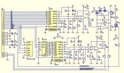
Attached below is a quick teaser pic of how far I got this evening. This is the display module that will plug into the digital motherboard. It contains it’s own little PIC uC (timing functions / sequencing), a pair of 12-bit DAC’s and is responsible for reading out the contents of the double-buffered display/record memory and generating the analogue signals for producing the analysers frequency domain display on an external analogue oscilloscope.
I hope to have the whole digital sampling/display section up an running over the Easter break.
Cheers,
Glen
I have, however, scrapped all the previous design work and redesigned to a higher performance specification. As another project on the go I am essentially designing and building my own AP-functional audio analyser system, so I figured I might as well make a companion spectrum analyser of comparable sophistication. I intend to use this spectrum analyser primarily to examine the harmonic spectrum of the THD residual extracted by the audio analyser.
As originally intended, the spectrum analyser will still work as stand-alone unit, providing X/Y/(Z) outputs to drive and generate a display on a conventional analogue oscilloscope, but I have, however, redesigned the digital sampling recorder/motherboard with an RS232 / USB interface for computer control / display / storage as well (I have been looking for a good excuse to upgrade from MS Visual Basic to MS Visual C, and the graphical interface for this project will be a good excuse).
I have also radically revamped the design by increasing the display / recorder resolution (for the horizontal sweep as well as the vertical axis) to 12-bits. This has significantly increased the complexity of the unit.
Anyway, besides this (12-bit resolution and PC interface), the basic operation of this part of the analyser is the same as the previous version I described in post 27:
http://www.diyaudio.com/forums/showthread.php?postid=1495589#post1495589
For the new design I have scrapped the discrete low-resolution R/2R ladder DAC’s and replaced with high performance 12-bit IC DAC’s (AD9752’s).
The design is complete on paper and as was the case with the now completed VGA analyser build previously documented in this thread, with this more ambitious project it is now just a case of entering the schematics into CAD, laying out the PCB’s, etching, loading, soldering and applying power.
Attached below is a quick teaser pic of how far I got this evening. This is the display module that will plug into the digital motherboard. It contains it’s own little PIC uC (timing functions / sequencing), a pair of 12-bit DAC’s and is responsible for reading out the contents of the double-buffered display/record memory and generating the analogue signals for producing the analysers frequency domain display on an external analogue oscilloscope.
I hope to have the whole digital sampling/display section up an running over the Easter break.
Cheers,
Glen
Attachments
G.Kleinschmidt said:... (I have been looking for a good excuse to upgrade from MS Visual Basic to MS Visual C, and the graphical interface for this project will be a good excuse).
Hi Glen, this (free) library should help you out with your Visual C GUI programming efforts.
Ultimate Toolbox
Good luck.
argofanatic
argofanatic said:
Hi Glen, this (free) library should help you out with your Visual C GUI programming efforts.
Ultimate Toolbox
Good luck.
argofanatic
There is a reason why they offer this after 10 years of selling, for free now.
It is quite outdated if you compare it with Visual Basic .NET, which has all the bells and whistles that they offer build-in. With the possible exception of graphing, for which you can use the free, Open Source ZedGraph libraries.
Visual Basic .NET Express is also free.
I just have gone through the selection process myself as I need a PC app for my new audio test set.
Designing for .NET gives you a modern, future-proof app.
Jan Didden
Microsoft has never equaled future proof.
If your prepared to adopt open source then most choices should be designed to avoid vendor and platform lock in. It is this that will give you the nearest thing to the illusive future proof label and what is more your mind share will not be held hostage to the corporate interests.
Comparable stacks exist in java, python and others.
cyteen said:Microsoft has never equaled future proof.
...
Maybe MS is "future-proof" rather than "future-ready"... 😀
Cheers!
Jan:
Would like to see some of your code - I have been looking for the RIAA routine I wrote for the '3577 and can't find it.
I have a graphing program which I paid for MSChart is difficult to deal with.
Would like to see some of your code - I have been looking for the RIAA routine I wrote for the '3577 and can't find it.
I have a graphing program which I paid for MSChart is difficult to deal with.
jackinnj said:Jan:
Would like to see some of your code - I have been looking for the RIAA routine I wrote for the '3577 and can't find it.
I have a graphing program which I paid for MSChart is difficult to deal with.
Jack, sorry, it isn't GPIB-based.
I'll send you the ZedGraph info if you want, VB .NET based. There is also a ZedGraph wiki where I found my info. I currently have a prototype app with ZedGraph running.
That said, you should get Vincent Himpe's "Visual Basic for Electronics Engineering Applications". He has developed a GPIB.dll that can be used to make a soft testbench on your PC controlling all kind of GPIB-based equipment, including the 3577. See book cover.
It's an Elektor book but Amazon carries it also:
http://www.amazon.com/Visual-Basic-...=sr_1_1?ie=UTF8&s=books&qid=1238010296&sr=1-1
We gave away a few copies at last years' BAF, but you weren't there....😉
Worth it's price for the things you do.
Jan Didden
argofanatic said:
Hi Glen, this (free) library should help you out with your Visual C GUI programming efforts.
Ultimate Toolbox
Good luck.
argofanatic
Thanks! I'll check it out.
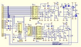
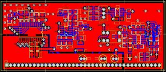
And here is this evenings effort - the 12-bit ADC module.
Features an in-amp differential input for noise rejection. 2V full scale input (with large allowable common-mode swing) either bipolar or unipolar (switched selected by a relay under uC control).
Unipolar input is for using the instrument as a spectrum analyser (sampling the output of the logarithmic detector) for a zero (votage) reference at the bottom of the display.
Bipolar input is for using the sampler as a low frequency digital storage oscilloscope - zero reference in the middle of the display.
I hope this is all making sense to you readers out there 😀
Cheers,
Glen
Attachments
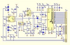
Here is the completed 12-bit ADC module.
An externally hosted image should be here but it was not working when we last tested it.
Attachments
- Status
- Not open for further replies.
- Home
- Amplifiers
- Solid State
- Homebrew Digital Sampling Audio spectrum analyser.