What distance was the measurement taken and what axis (on axis with the tweeter?) If you work out the geometry of the triangle between the mic, tweeter and mid, would there potentially be 8cm difference between the distance between the tweeter and the mic, and the mid woofer and the mic?
Also I note that the gating on the tweeter measurement is different to the gating on the mid measurement, you should probably bring the two into alignment.
Are the measurements shown with the active filter in use? If they are can you do the measurements with the raw drivers?
Tony.
Thanks for the assistance .
The Mic is at 900mm and aligned between the two drivers on axis. I am measuring inside.
The measurements below are Time Zero Locked without the XO and it shows a 3cm difference when measured with First Positive Peak, but physically there is only 10mm difference when the tweeter is measured from the radiating surface and the Mid is measured from the Cone cap, you would add 10mm approx to the base of the cone cap.
Any more thoughts.
I'm happy with the response curve I just need to get on top of the phase!
Thanks again🙂
Attachments
ok I think from memory there is a bug in holm where you need to click on auto (for time zero auto detect) twice for it to get the right time zero. That latest measurement does not look like the tweeter measurement is properly aligned.
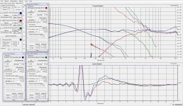
The two drivers appear to be about 70 degrees apart (which is perfectly normal), this would tend to indicate that you would be best off with 1 order difference between tweeter and midbass electrical order.
I'm not sure from the plots whether that means an extra order on the tweeter or the woofer is warranted (but I suspect the tweeter), or whether this will give you the desired acoustic slope.
If you have the option to try different orders I would try to change the order whilst maintaining the acoustic slope (something I have been able to do with passive XO's) and you might start to see a better phase match.
Another thing that would reveal how well your phase is matching would be a measurement of both drivers (with the filters) with one reversed to see how much of a reverse null you get. I suspect with nearly 90 deg of phase difference there will not be much of a reverse null.
all the above assumes that the desired acoustic crossover is in fact even order. If it is odd order you probably don't have anything to worry about 🙂
Tony.
DQ828,
Have you selected "Keep in/out stream active"? You must do that and also select "Start Stream" for the "Time zero lock" function to work. This needs to be done first, before measurements and setting the offset.
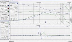
I ask because your first graph show the 2 individual driver responses and both together. It is clear from that SPL chart that the driver timing is very good. There is very good SPL support in the XO range. The phase chart however shows the timing to be poor. This suggest he timing lock was not properly activated. This can happen when start stream is selected. Holm will indicate whether the stream is active at the bottom of the Holm window
Your other charts show different timing and again the stream not being activated can be the cause.
Have you selected "Keep in/out stream active"? You must do that and also select "Start Stream" for the "Time zero lock" function to work. This needs to be done first, before measurements and setting the offset.
I ask because your first graph show the 2 individual driver responses and both together. It is clear from that SPL chart that the driver timing is very good. There is very good SPL support in the XO range. The phase chart however shows the timing to be poor. This suggest he timing lock was not properly activated. This can happen when start stream is selected. Holm will indicate whether the stream is active at the bottom of the Holm window
Your other charts show different timing and again the stream not being activated can be the cause.
ok I think from memory there is a bug in holm where you need to click on auto (for time zero auto detect) twice for it to get the right time zero. That latest measurement does not look like the tweeter measurement is properly aligned.
The two drivers appear to be about 70 degrees apart (which is perfectly normal), this would tend to indicate that you would be best off with 1 order difference between tweeter and midbass electrical order.
I'm not sure from the plots whether that means an extra order on the tweeter or the woofer is warranted (but I suspect the tweeter), or whether this will give you the desired acoustic slope.
If you have the option to try different orders I would try to change the order whilst maintaining the acoustic slope (something I have been able to do with passive XO's) and you might start to see a better phase match.
Another thing that would reveal how well your phase is matching would be a measurement of both drivers (with the filters) with one reversed to see how much of a reverse null you get. I suspect with nearly 90 deg of phase difference there will not be much of a reverse null.
all the above assumes that the desired acoustic crossover is in fact even order. If it is odd order you probably don't have anything to worry about 🙂
Tony.
First I'll try pressing the Zero Time Lock twice & see how I go, thanks.
DQ828,
Have you selected "Keep in/out stream active"? You must do that and also select "Start Stream" for the "Time zero lock" function to work. This needs to be done first, before measurements and setting the offset.
I ask because your first graph show the 2 individual driver responses and both together. It is clear from that SPL chart that the driver timing is very good. There is very good SPL support in the XO range. The phase chart however shows the timing to be poor. This suggest he timing lock was not properly activated. This can happen when start stream is selected. Holm will indicate whether the stream is active at the bottom of the Holm window
Your other charts show different timing and again the stream not being activated can be the cause.
Yes I did have "Keep in/out stream active" ticked but I have never pressed the "Start Stream" button, I'll give it a go thanks.
Well I made sure the Time Zero Locked was working all of the measurements have the same number of Offset Samples, I also made sure the Audio Stream was started but am getting much the same measurement.
I'm going to modify the the XO so I can unplug the Notch filter & the All Pass filter and see if that affects the phase measurement.
Thanks for the advice, I'll be back 🙂
I'm going to modify the the XO so I can unplug the Notch filter & the All Pass filter and see if that affects the phase measurement.
Thanks for the advice, I'll be back 🙂
Attachments
The first chart (Post 277) was not time locked. The phase tracking of both drivers together is not properly following that of the 2 individual drivers.
This last chart looks believable, so it now seems to be sorted. 🙂
There is a very slight slip to the time lock amounting to only 40° at 20kHz so it is of no real concern for that set of measurements.
It does raise a concern however if the time lock is sometimes slipping greater distances. I have one notebook PC that would occasionally slip timing a very significant distance and often had to start over on my measurement efforts. Some days were worse than others, but I was never able to completely eliminate it. A different notebook does not ever have that issue. I have no idea how common a problem it is for different PCs. I must not be too common as there would be more comments here.
Repeated measurements should be identical for IR location and phase so if there is a shift seen with repeated measurements from the start of a timing session to the end there is a problem.
I am not suggesting you have this problem. I'm just mentioning it so you know it can exist in some cases.
I have a PC with a Behringer UCA202 connected to a Technics SA-600 receiver. I also have a Dayton Audio EMM6 microphone and Blue Icicle XLR to USB converter mic preamp. I am trying to figure out how to calibrate this. Can anyone help?
I have a PC with a Behringer UCA202 connected to a Technics SA-600 receiver. I also have a Dayton Audio EMM6 microphone and Blue Icicle XLR to USB converter mic preamp. I am trying to figure out how to calibrate this. Can anyone help?
A HOLM starter guide
I already been through that, I started this journey there, and it did not answer the question. I assume what I really need is an XLR to RCA cable to complete the correct loopback. Thanks for the response.
Last edited:
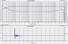
I got my cables from Monoprice today and the calibration seemed pretty good now. I had to adjust volume and mic gain slightly but overall here is the graph. How does this look?

I got my cables from Monoprice today and the calibration seemed pretty good now. I had to adjust volume and mic gain slightly but overall here is the graph. How does this look?
View attachment 454229
I cannot remember exactly what mine looked like but I'm pretty sure the line remained flat further into the LF and maybe a bit more into the HF,
It definitely seems to be rolling off too early on the low end (and top end).
I'd expect flat down to at least 20Hz yours is rolling off steeply at around 50Hz.
Also the phase looks a bit wonky in the calibrated response. I would expect it to be almost completely flat.
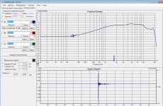
Attached is an uncalibrated response curve of my focusrite scarlet 2i2 in unbalanced mode with 96Khz sampling rate. I don't have a calibrated one as I have a problem with holm crashing when I try to calibrate (it seems to be an issue with windows7 64bit)
Now this particular card is very good so don't think you have to have something this good, but it is along the lines of what I would expect to see. Phase may kick up more in the high frequencies than this. But on the rare occasions I have managed to do a calibration the phase has been completely flat after calibration.
Tony.
I'd expect flat down to at least 20Hz yours is rolling off steeply at around 50Hz.
Also the phase looks a bit wonky in the calibrated response. I would expect it to be almost completely flat.
Attached is an uncalibrated response curve of my focusrite scarlet 2i2 in unbalanced mode with 96Khz sampling rate. I don't have a calibrated one as I have a problem with holm crashing when I try to calibrate (it seems to be an issue with windows7 64bit)
Now this particular card is very good so don't think you have to have something this good, but it is along the lines of what I would expect to see. Phase may kick up more in the high frequencies than this. But on the rare occasions I have managed to do a calibration the phase has been completely flat after calibration.
Tony.
Attachments
Hi Doug, first thing I would probably try and get your gating a bit lower than 2Khz if you can. If you can't you probably need to reposition to get less reflections.
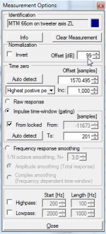
Next thing you will probably want to click on options and add about 90 to 99db to the measurement (this is more important for PCD as it expects a measurement somewhere between about 60 and 90db). You can set it back to 0db after the export. (third screenshot)
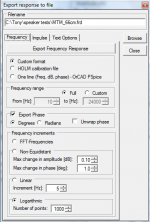
When you do the export click export on the measurement. You will most likely need to change some settings. On the frequency tab if you set like I have in the attached screenshot you should be right for Speaker Workshop or PCD.
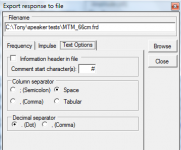
On the text options tab set as per the other screenshot (again ok for speakerworkshop and PCD). The default settings generally don't work too well.
Once you have set your settings, I'd suggest clicking browse, change from .txt to all files and put in the path and your filename with a .frd extention.
You then need to go back to the frequency tab and click on export frequency response.
You should be able to import then into either pcd or speaker workshop.
Next thing you will probably want to click on options and add about 90 to 99db to the measurement (this is more important for PCD as it expects a measurement somewhere between about 60 and 90db). You can set it back to 0db after the export. (third screenshot)
When you do the export click export on the measurement. You will most likely need to change some settings. On the frequency tab if you set like I have in the attached screenshot you should be right for Speaker Workshop or PCD.
On the text options tab set as per the other screenshot (again ok for speakerworkshop and PCD). The default settings generally don't work too well.
Once you have set your settings, I'd suggest clicking browse, change from .txt to all files and put in the path and your filename with a .frd extention.
You then need to go back to the frequency tab and click on export frequency response.
You should be able to import then into either pcd or speaker workshop.
Attachments
Thanks Tony,
I did find the MDT 20 file on the desktop loaded with data. Let me tell ya it wasn't pretty or smooth (keystrokes) but got it.
The gating is mysterious, starring me in the face, and eventually moved by itself. It started of around 300 with static looking lines but when it moved to 1,500 the line smoothed out nicely and looks like the manufacture response.
EDIT - did find the gating setting
And yes looking forward to uploading in a speaker workshop program.
Last edited:
Question on interpretation of HI harmonic distortion plots
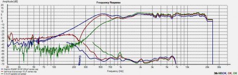
In the test shown below I question why the 3rd Harmonic distortion test results where higher (green line) in the 400-800 hz range since the green line represents a steeper roll off the freq. and thus preventing more low freq. info. getting to the tweeter and causing more distortion.
In the test shown below I question why the 3rd Harmonic distortion test results where higher (green line) in the 400-800 hz range since the green line represents a steeper roll off the freq. and thus preventing more low freq. info. getting to the tweeter and causing more distortion.
Attachments
Last edited:
Yes, I've noticed this in my measurements too, and I think it's the crossover network causing it.
The true horror of passive crossovers ! (Page 1) - Reference - AVI HiFi Forum
The true horror of passive crossovers ! (Page 1) - Reference - AVI HiFi Forum
I would suggest that it is the fact that % uses the fundamental level as a reference. This reference is falling creating a greater % even if the level of the harmonics is also falling.
- Home
- Design & Build
- Software Tools
- HOLMImpulse: Measurements in practice