Overall gross phase linearisation of an existing box was the goal. Just to get rid off the excess phase from the allpass behaviour of the crossover. For me the test was meant to empirically back what I already had found out with a scope test: to find the xover-freqs and the slopes for this box, to be compensated with the theoretical reverse allpass function and additionally and most important, to get rid of the excess group delay in the bass frequencies near the lower cutoff. It's a bass reflex design, 4th order hence, and this makes the deep bass lag way behind. Now I have synchronous bass, that is very noticable not only in timing but in timbre also (see below, on that). The effect is even more pronounced with my nearfield coax 2ways with a 6th-order alignment at 50Hz. Still not deep bass of course, but now its tight bass. Optically a 60Hz square wave now looks perfect.
BTW after this phase corrections I now can hear the effect of absolute polarity, if you want to try play the linked test file I made for this in a loop, four of the "bassdrums" are "fatter" than the other four (eight in total). The signal is 60Hz@0dB + 120Hz@-6dB&90deg phase with an exponential decay and pretty asymmetric but with close to zero DC content, similar to the steady-state test signal used for acoustic/electric phase check meters. With real bassdrums I now hear the effect of the "fatter" polarity ("correct" in that above sense), too.
http://www.freefileserver.com/355442
Klaus
Hey Guys,
The problem with impules response alignment is that the peak of the impulse is where the highest frequencies are, so if you align the peaks, of say the HF and LF, your joining the "wrong ends of the stick" as it were.
Examining the relative slopes of the phase trace through the crossover region and getting them to agree seems to be the best way to get these components into alignment.
By adjusting the arrival time so you get the phase slope to be horizontal for one band you know that you are looking at when that energy is arriving. Without changing the delay time you now can see if the the other band is arriving early or late by looking at the phase slope.
It's this area of interaction between bands that needs attention.
Two signals of equal amplitude will have the most interaction.
Good points, Ferrit37, and Ask has made us aware of how to avoid these and similar kinds of errors with his software.
Just for clarification, my approach was and is (for now) to generate overall correction data for the speakers which themselves are completely unchanged. A further step will be to change these 3ways into active speakers with active convolver based crossovers in the final project stage, then the interdriver alignment issues will raise their ugly heads as I don't pan to modify the enclosure to mechanically time-align the acoustic centers of the drivers.
- Klaus
Hey Klaus,
My main job is as systems alignment engineer, I have the luxury of usually dealing with all DSP driven systems, now if they would just let me use a "bulldozer" I'd tune the room for them. 😱
My main job is as systems alignment engineer, I have the luxury of usually dealing with all DSP driven systems, now if they would just let me use a "bulldozer" I'd tune the room for them. 😱
Ferrit37 said:Hey Guys,
The problem with impules response alignment is that the peak of the impulse is where the highest frequencies are, so if you align the peaks, of say the HF and LF, your joining the "wrong ends of the stick" as it were.
Examining the relative slopes of the phase trace through the crossover region and getting them to agree seems to be the best way to get these components into alignment.
By adjusting the arrival time so you get the phase slope to be horizontal for one band you know that you are looking at when that energy is arriving. Without changing the delay time you now can see if the the other band is arriving early or late by looking at the phase slope.
It's this area of interaction between bands that needs attention.
Two signals of equal amplitude will have the most interaction.
This is a very good information. Thank you!
I am away from home for almost 2 months so won't be able to test your method very soon. That may also explain why, my measured position didn't agree with the position I would have chosen by ear. When I'll get back, I will post my results here and may ask for more guidance...
I didn't get the "bulldozer" thing...
The only thing that I can manipulate is the direct sound from the loudspeakers, which is only a small part of what we finally hear.
Many times I've been asked to "tune the room", when poor building design, bad acoustics, reflections etc, could possibly be fixed with the bulldozer 😉
Many times I've been asked to "tune the room", when poor building design, bad acoustics, reflections etc, could possibly be fixed with the bulldozer 😉
Is this normal?
Hi,
I need to take measurements of my set of speakers, and I recently started using HolmImpulse for that.
I use the following equipment: a UCA202 USB audio interface.
Without any mic connected I got the response I am showing below. Is this normal?
Josep
Hi,
I need to take measurements of my set of speakers, and I recently started using HolmImpulse for that.
I use the following equipment: a UCA202 USB audio interface.
Without any mic connected I got the response I am showing below. Is this normal?
Josep
Attachments
Hi,
I need to take measurements of my set of speakers, and I recently started using HolmImpulse for that.
I use the following equipment: a UCA202 USB audio interface.
Without any mic connected I got the response I am showing below. Is this normal?
Josep
No this is not normal - I'm not able to see what is wrong in your setup
- Try 'Data Analysis' > 'Save waveforms when measuring' Then you can see what the recorded signal was
- Remember to check your windows mixer settings
- Perhaps try a lower samplerate
Last edited:
Thanks ,
I still do not know what is going on, exactly, but after experimenting some more, I found out that the UCA202 is feeding part of the output signal to its input interface... this may explain (I guess) the above results, as well as some other erratic measurements I got, which I thought did not make sense.
Additionally, I noticed that Holmimpulse used to complain about clipping levels of input signal when using the input and output interfaces of the UCA202 at the same time.
It also complained about the signal being too low when the microphone input was the built in line-in of the laptop, and no microphone was connected, but it does not complain when I do not connect a Microphone to the input of the UCA202. I wonder why this is.
In any case, it looks like the UCA202 is either inadequate to being driven simultaneously through its input and output, or my unit is defective...
Using the UCA202 for input and a different device for output seems to produce (apparently) more sensical results.
Thanks ,
Additionally, I noticed that Holmimpulse used to complain about clipping levels of input signal when using the input and output interfaces of the UCA202 at the same time.
That is simply when the recorded level has reached 100% during recording
(you can see the recorded waveform using Audacity - then you can see if the signal has indeed been clipped)
You know, wave files are easy to open and display and being able to look at them from within the program (Audacity is expensive and not a very efficient program for this anyways) would be a great feature.
Audacity "The Free, Cross-Platform Sound Editor" .
Not expensive or hard to use.
I'm sorry, my mistake. I was thinking that this was the old "Cool Edit" which is now a very expensive piece of software from Adobe. I was confused. I still use "Cool Edit".
I do not know if this question have bee asked before, is it possible to let three mics to be mixed in a custom built mic preamp and then do HOLMImpulse nearfield measurements in one go on a three way system?
There could also be a switch in this mixing preamp for selecting individual mics.
There could also be a switch in this mixing preamp for selecting individual mics.
I do not know if this question have bee asked before, is it possible to let three mics to be mixed in a custom built mic preamp and then do HOLMImpulse nearfield measurements in one go on a three way system?
You will not get more information doing this compared to making three measurements with same same mic and then sum the measurements afterwards
Currently you have 2 channels: Left / Right - If you choose Mono the two inputs will be mixed.There could also be a switch in this mixing preamp for selecting individual mics.
I just find it tedious and time consuming to move the mic back and forth and up and down all the time!
Is there not also a second benefit of the mics being stationary placed once for all measurements, avoiding small mic movements that otherwise would show in the resulting graphs?
Is there not also a second benefit of the mics being stationary placed once for all measurements, avoiding small mic movements that otherwise would show in the resulting graphs?
Ah yes, "Cool Edit" Have not used it but have heard good things about it.
I've used Goldwave for years and really like it. East to use - not expensive, either.
I've used Goldwave for years and really like it. East to use - not expensive, either.
I just find it tedious and time consuming to move the mic back and forth and up and down all the time!
Is there not also a second benefit of the mics being stationary placed once for all measurements, avoiding small mic movements that otherwise would show in the resulting graphs?
Any measurement that is hyper-sensitive to the mic location is not of much use. Near field measurements can be very sensitive at higher frequencies, but they are also not correct or meaningful at those frequencies either. Far field measurements are seldom very sensitive to the mic location. If they were then that would imply and extremely narrow aspect to the directivity which is not really possible.
Hey Guys,
The problem with impules response alignment is that the peak of the impulse is where the highest frequencies are, so if you align the peaks, of say the HF and LF, your joining the "wrong ends of the stick" as it were.
Examining the relative slopes of the phase trace through the crossover region and getting them to agree seems to be the best way to get these components into alignment.
By adjusting the arrival time so you get the phase slope to be horizontal for one band you know that you are looking at when that energy is arriving. Without changing the delay time you now can see if the the other band is arriving early or late by looking at the phase slope.
It's this area of interaction between bands that needs attention.
Two signals of equal amplitude will have the most interaction.
Wow I am having a hard time with this concept - phase is one of those things that makes my head hurt in more ways than one.
So in simple words are you saying that it's just better not to have some weird jump in the phase at the crossover region more than to make the phase response reside on the 0 mark for a large portion of the frequency response?
I wanted to experiment with the same concept Klaus was, but using DSP in the middle of the entire recording/playback chain in order to linearize the phase response for at least the midband and high frequencies. So what pattern should I be trying to follow if I wanted my recordings to come out "phase linear"? Maybe this is a flawed concept to begin with but it was just one of those things I wanted to mess with.
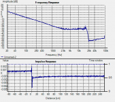
This is a loopback of the microphone I plan on using for everything on the recording. It is going through the exact pre-amp and playback chain I plan to record and monitor on. It is a 2-way bass reflex so the best I can hope for is to correct the mids and highs. The crossover is at 1.8kHz. It's not the best screen shot but I accidentally deleted my other much better measurements the other day. The bass region looks like a peculiarity of the measurement or the proximity effect.
An externally hosted image should be here but it was not working when we last tested it.
Last edited:
Hey Key,
Let's see if we can make the headache go away 🙂
In a dual FFT measurement system we have two measurement points to get our signals from, one is the reference (the signal we put in) and the other is the Measure (the signal we get out) in simple terms the difference between these signals is what our system has done to the signal as it passed through, we call this a "transfer function".
Now our measurement system "knows" when the signal went in and when it came out, and we can use this time difference to figure out the "time of flight" which we need to remove from our measurement.
Now that we have synchronized our two signals any other delays must be inherent in the DUT and this shows up in the phase response trace. Where the trace is Horizontal the energy of the two signals arrived together, where the trace slopes downward the measurement signal has arrived later and if the signal slopes upward it has arrived earlier.
So by looking at the relative slope of the phase trace compared to another point we can determine "when which energy arrived when"
Getting all the energy to arrive at the same time is our goal but it get's complicated by "arrive where?"
You can compensate for physical offset between loudspeaker components, but only for one place, but let's leave that problem for another time 🙂
We want to "glue" our different drivers together so that the region of crossover where the two bands overlap arrive at the same time, this is our region of interaction that we need to manage.
Now once we've got them playing nice together what about the overall phase response of the driver. Each driver will have it's own inherent phase curve but most top quality drivers are minimum phase over most of their usable region.
It is possible with modern DSP and allpass filters to fix the overall phase response to give a linear or as you say phase trace sitting on the zero line, the price you pay is of course latency, especially at LF.
You mention fixing the phase in your recording chain, but what would happen if you played it on another loudspeaker system?
I personally think a better goal would be an accurate recording chain and an accurate playback chain, each independant of the other.
Hope this has helped.
- Home
- Design & Build
- Software Tools
- HOLMImpulse: Measurements in practice