Hi Mogens,
I'll be happy to review your revised documentation. You can post it on a file service, send me a private message with the link to the file and I'll download it there.
Regarding the PreAmp, I'm quite confident, but not 100%, that my friend uses a HolFi. I'll check for you.
Regards,
Winfried
I'll be happy to review your revised documentation. You can post it on a file service, send me a private message with the link to the file and I'll download it there.
Regarding the PreAmp, I'm quite confident, but not 100%, that my friend uses a HolFi. I'll check for you.
Regards,
Winfried
Hi Winfried,
That would be great, He will probably not let you take it apart 🙂. But some good closeup pictures of the top of the PCB might tell us something.
Holfi uses very low input impedance on their power-amps. 825 ohm so not all pre-amps are happy to drive them.
Cheers,
Mogens
That would be great, He will probably not let you take it apart 🙂. But some good closeup pictures of the top of the PCB might tell us something.
Holfi uses very low input impedance on their power-amps. 825 ohm so not all pre-amps are happy to drive them.
Cheers,
Mogens
Hi all,
my name is Alfred Rosenkraenzer, I worked 36 years as a design engineer, mainly on analog and digital signal designs.
Now I am on early retirement. My homepage is: www.alfredrosenkraenzer.de
I repaired Winfrieds Holfi.
On one channel Q3 in the preamp was dead. Therefor the offset regulation was at one end leading the relays to be turned off.
I replaced D17 to a 1N4004 and added also some directly at the relay coils, on both channels.
On the second channel R27 was broken. By touching it the relays turned on, otherwise turned off.
The standby switch and the relays are ok. But the contacts of K1 are in danger due to the high switch on current when the big caps are loading the 220 uF.
The 0.22 Ohm will not help much.
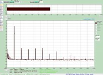
Please find attached a spectrum of a 1060 Hz sine output 1 W at 8 Ohm (8 Vpp). Done with a RME Babyface pro USB interface and AudioTester SW.
It is ok for an amp without feedback.
I also added the simulation files of the amp and the standby circuit. I used the free version of Simetrix 8.3.
There is also a small simulation of the rush in current.
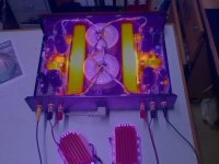
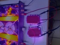
Just for fun there are two thermo pictures of the amp and the load.
Alfred
my name is Alfred Rosenkraenzer, I worked 36 years as a design engineer, mainly on analog and digital signal designs.
Now I am on early retirement. My homepage is: www.alfredrosenkraenzer.de
I repaired Winfrieds Holfi.
On one channel Q3 in the preamp was dead. Therefor the offset regulation was at one end leading the relays to be turned off.
I replaced D17 to a 1N4004 and added also some directly at the relay coils, on both channels.
On the second channel R27 was broken. By touching it the relays turned on, otherwise turned off.
The standby switch and the relays are ok. But the contacts of K1 are in danger due to the high switch on current when the big caps are loading the 220 uF.
The 0.22 Ohm will not help much.
Please find attached a spectrum of a 1060 Hz sine output 1 W at 8 Ohm (8 Vpp). Done with a RME Babyface pro USB interface and AudioTester SW.
It is ok for an amp without feedback.
I also added the simulation files of the amp and the standby circuit. I used the free version of Simetrix 8.3.
There is also a small simulation of the rush in current.
Just for fun there are two thermo pictures of the amp and the load.
Alfred
Attachments

Dear Alfred.Hi all,
my name is Alfred Rosenkraenzer, I worked 36 years as a design engineer, mainly on analog and digital signal designs.
Now I am on early retirement. My homepage is: www.alfredrosenkraenzer.de
I repaired Winfrieds Holfi.
On one channel Q3 in the preamp was dead. Therefor the offset regulation was at one end leading the relays to be turned off.
I replaced D17 to a 1N4004 and added also some directly at the relay coils, on both channels.
On the second channel R27 was broken. By touching it the relays turned on, otherwise turned off.
The standby switch and the relays are ok. But the contacts of K1 are in danger due to the high switch on current when the big caps are loading the 220 uF.
The 0.22 Ohm will not help much.
Please find attached a spectrum of a 1060 Hz sine output 1 W at 8 Ohm (8 Vpp). Done with a RME Babyface pro USB interface and AudioTester SW.
It is ok for an amp without feedback.
I also added the simulation files of the amp and the standby circuit. I used the free version of Simetrix 8.3.
There is also a small simulation of the rush in current.
Just for fun there are two thermo pictures of the amp and the load.
Alfred
A friend of mine want to have more modern resistors in the signal path of the Power NB3. Do any of you have a schematic diagram here?
Good Christmas to all of you.
Best regards Jesper 🙂