Hi Torben,
I have updated the schematic with the values from your picture. It would be good if we could voltages documented also.
integra_rev_02.pdf - Google Drive
Cheers,
Mogens
I have updated the schematic with the values from your picture. It would be good if we could voltages documented also.
integra_rev_02.pdf - Google Drive
Cheers,
Mogens
Hi Mogens
Fantastic, again - looks very good…..I tried with new resistor, but still no luck. Using the schematic I checked voltages, they were good on left side but right side only good until the 2240BL/970BL. I have ordered new and they will soon be at my doorstep…….
When I change them, ill check PS part of schematic - and the output relay……
Regards Torben
Hi Torben,
If you could add some voltage measurements on both the good and bad channel we could probably calculate where it's going wrong.
Judged on the pictures I thought that some of soldering on the input transistors could do with a clean up.
Where did you order the 2240BL/970BL? As far as I know they have not been in production for some years. I only know of an SMD version of the part. So please be aware of fakes.
Cheers,
Mogens
Hi Mogens
The local Brincks Elektronik (Elextra) had som 2240BL (old ones) but only 970GR so I have ordered 3 set of 3 pcs of 970BL on ebay - not from china but UK and France...... I ll be carefull with them, thanks.
I ll add voltage on the good and the bad channel :- )
Regards Torben
The local Brincks Elektronik (Elextra) had som 2240BL (old ones) but only 970GR so I have ordered 3 set of 3 pcs of 970BL on ebay - not from china but UK and France...... I ll be carefull with them, thanks.
I ll add voltage on the good and the bad channel :- )
Regards Torben
Hi Torben,
Ok, if you run into trouble I might be able to find a few, perhaps slightly used, in my stash.
Even with only the PSU supply voltages we should be able to some calculations. But, of course more measurements makes it easier.
Mogens
Ok, if you run into trouble I might be able to find a few, perhaps slightly used, in my stash.
Even with only the PSU supply voltages we should be able to some calculations. But, of course more measurements makes it easier.
Mogens
Hi Mogens
I have meassured a little bit around, does it make any sense to you? When meassures are in blue color both channels are the same.....if red numbers, the bad channel meassures different. Notice Im still only at 150V AC power.
2240/970 not changed yet - sounds great if you have som spare.....some ebay should be arriving soon. If you have 970BL i would like to buy :- ) i need 3 pcs. I trust the 2240bl from Brick/Elextra.
Hilsen Torben
Attachments

Hi Torben,
I totally lost track of this thread here in the summer. Did you get it sorted out?
Mogens
I totally lost track of this thread here in the summer. Did you get it sorted out?
Mogens
Hi Mogens
No problem......Yes Im close. :- ))
I did get the transistor and they looked fine and genuine, I put them in and everything - almost - went well.
BR Tb
No problem......Yes Im close. :- ))
I did get the transistor and they looked fine and genuine, I put them in and everything - almost - went well.
- I run full power, 230V - also without the variotrafo.
- I have equal sound on both channels before the protection relay…..
- Heat is fine - and equal L / R
BR Tb
Hi Torben,
Good news.
As said previously, I have a NB-3 power amplifier which I have not heard in a controlled listening setup yet. I just bought it as the price was reasonably and I wanted a peek inside to know what all the fuzz is about.
I suspect some of the charm is that these amplifiers are not low distortion at all 🙂
Mogens
Up and running......./bias/dc-offset
Hi Mogens
Im up and running - Im listening to the holfi now :- )
I changed the relay, but had the same result, no music after the relay...…..
Well, the relay was probably allright.
It was me who wasnt familiar with the standby switch.....I found that the relay actually clicked when the standby button was in "upper position". And then there were music!
Standby state is something you "switch on" on this Holfi.
So thank you again for helping me and the amp...:- )
I have not fully adjusted DC-ofset and bias.
I have 15-16 mV bias and ca. 38 degrees directly on transistors - I plan to raise to 20mV?
I have within +/- 10 mV dc-offset - but the testpoint TP1 / TP2 meassure 7v.HIFI4ALL Forum: Holfi NB2 SE Power DC offset?
Do you or anyone else know about adjusting Holfi….I found this thread for NB2
About the sound so far, not fully adjusted - very nice warm indulging sound. It will probably get a little more edge when bias is raised.
I never heard a Holfi before, but have heard people speak of Holfi sound - and I agree.
Last edited:
Hi Mogens
I tried adjusting again…..
It is possible to get the TP1/2 close to 0V - at least within 200-300 mV - and the dc-offset might have been a little lower and more stable.
I have raised the bias to 19 mV...
Waiting time see if its stable...
BR Torben
I tried adjusting again…..
It is possible to get the TP1/2 close to 0V - at least within 200-300 mV - and the dc-offset might have been a little lower and more stable.
I have raised the bias to 19 mV...
Waiting time see if its stable...
BR Torben
Hi Torben,
Sounds good that you have it up and running now. If it were me I would adjust TR1 so TP1 is as closed to 0V as possible. 200 - 300 mV is fine. That means that the servo is able to sving equally to either side of it's supply voltage.
As long at the servo can deliver enough voltage it's able to keep the amplifier output close to 0V DC.
Does this explanation make sense?
Mogens
Hi Mogens
That makes sense. Its stable, i have played for some time now.
Its a very amplifier, i think it has power and musicality….i am happy with, among my other amplifiers. I think youre right about the construction, which give a warm and intrigent sound. It delivers a sound that is nice and easy - musicality before details.
thanks Torben
Hi Torben,
That sounds great. No pun intended. It is puzzling how certain types of distortion manifest itself.
Take care,
Mogens
That sounds great. No pun intended. It is puzzling how certain types of distortion manifest itself.
Take care,
Mogens
Hello Mogens and Torsten, nice to meet you. I'm strugling with a Holfi Power 8. It came in working, but with extensive leaking of filter caps. I ended up replacing all caps , after cleaning the acids of the pcb. Now it fires up, but there is no bias current and 2,5V DC on both channels. Schematics are not available. Any of you have any idea if the integra might be somewhat the same ?
Thanks, Phil , The Netherlands
Thanks, Phil , The Netherlands
@xinix; Sorry I have missed your message. Either I didn't get notified or I simply missed it. Do you have som close up pictures of the output stage? I think we would be able to draw the schematic. Hofli amplifiers are reasonably similar.
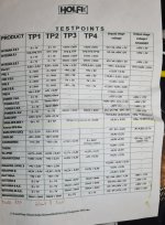
@bambadoo: thanks. Very usefull.
Mogens
@bambadoo: thanks. Very usefull.
Mogens
@Xinix - i didnt get a "note" on your message either. I had to change the transistors in my integra 8.
@Bambadoo - very very nice :- ) and useful. I see Im running a little high!
I really like my amplifier!
@Bambadoo - very very nice :- ) and useful. I see Im running a little high!
I really like my amplifier!
Hello everybody, sorry for the late reply. I did manage to fix the amp with the Integra schematics elsewhere in this thread. They are the same as the Power8.
It turned out to be a damaged via in the + rail to the output transistors. It's up and running ever since. Not a big fan of the brand though. Low PCB quality.
It turned out to be a damaged via in the + rail to the output transistors. It's up and running ever since. Not a big fan of the brand though. Low PCB quality.
- Home
- Amplifiers
- Solid State
- Holfi Integra