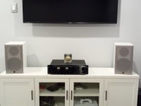
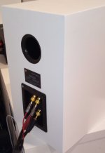
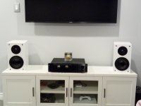
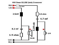
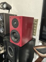
Finally got my babies finished. I ended up adding an 8.2 ohm resistor inside the box between the hi input binding post solder tab and the wire to the hi section of the crossover, so I didn't have to change the 6.8 ohm on the board and can easily adjust later for different setup. These do sound really good.
Attachments
Last edited:

Be aware of the effect of burn-in!
I bought the kit recently. Right after assembling, it sounds plain. I ran 20 Hz sine wave on them for around 10 hours. Bass came out and was amazingly full. I decided to run the Stereophile burn-in track for another 10 hours at a reasonably loud level. The speakers sounded bright afterwards. The bass level did not seem to change much based on the KRK level meter app on my iPhone. Sound level jumps up around 2K Hz and are 5 dB higher above it.
My listening room is 15" X 20". I placed the speakers against the short wall. They are 3 ft away from back wall and 5 ft from the side walls. I tried them in my large living room and kept them 5 ft away from any wall. They sounded clean/dry and required a lot more amp power to reach loud listening level.
So I replaced the 6.8 uF capacitor with a 4.7 uF blue Rifa PP film capacitor. This reduced the brightness. XSim indicated substantial drop of tweeter level at 2K Hz. This may explain the change. But the bass is still too weak to my taste. I will let them play more before replacing the inductors with 2.5 mH ones.
I think the kit has the potential to be great. I listened to the tweeter and woofer output at 2K Hz. Unlike some of my other speakers, the woofer and tweeter sound quite coherent. The only concern I have is that violins can sound harsh for some recordings. Maybe I also need the 8.2 ohm resistor in the end.
Just finished my speakers and in the middle of breaking them in. Went with the 2.2se crossover, went with the 2.5mh inductor, Clarity 4.8uf, a better resistor for the tweeter, and some Dayton DFFC bypass caps- .01uf tweeter/ .2uf for the woofer. They sound great! A little bass heavy, I don't think you would need a sub for music but these will be used as my mains for my surround system. I might try a 2.2mh or 2.0mh,but I will use them like this for a while and eventually measure them.


Hi!
can please somebody help me with the croosover componets for this other Hivi / swans model...
https://www.swanspeakers.com/product/view?id=138
the drivers are easy to identified...information about the crossover not so easy to find
can please somebody help me with the croosover componets for this other Hivi / swans model...
https://www.swanspeakers.com/product/view?id=138
the drivers are easy to identified...information about the crossover not so easy to find
Sorry, couldn’t find anything about this one, only found the crossover schematics for the older one - Swans M1.
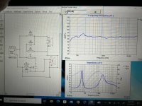
these are my measurements and the crossover.
tools list:
-motu m4
-aiyima a07
-smsl a300
-isemcon EMX-7150
measurement are taken in room with room eq, woofer and port nearfield measurement.
stock crossover:

definitive crossover:
10ohm resistors on the woofer are 20w, the 10 ohm resistor on the tweeter is 5w;
on the woofer use a 0.8mH inductor (jantzen ferrite core 0,8mH - 1,0mm, 0,182ohm rdc) less resistance is better.

Lastly a crossover based on the original one but it has not been tested or measured.

Regarding the THD you can give 18v to the tweeter without any particular distortion, and more than 22v on the woofer.
These are the changes made to the cabinet:
6mm chamfering on the baffle
2mm CTK bitomous dampening material
CTK CaiMat 8 500x400mm
tools list:
-motu m4
-aiyima a07
-smsl a300
-isemcon EMX-7150
measurement are taken in room with room eq, woofer and port nearfield measurement.
stock crossover:
definitive crossover:
10ohm resistors on the woofer are 20w, the 10 ohm resistor on the tweeter is 5w;
on the woofer use a 0.8mH inductor (jantzen ferrite core 0,8mH - 1,0mm, 0,182ohm rdc) less resistance is better.
Lastly a crossover based on the original one but it has not been tested or measured.
Regarding the THD you can give 18v to the tweeter without any particular distortion, and more than 22v on the woofer.
These are the changes made to the cabinet:
6mm chamfering on the baffle
2mm CTK bitomous dampening material
CTK CaiMat 8 500x400mm
Attachments
If that was in response to me, I have no idea why you think that.
A resistor across the amplifier terminals is never a good idea, and is a potential fire hazard. It is bad information to even think of doing such a thing. I explore you to remove this resistor for your health and safety.
A resistor across the amplifier terminals is never a good idea, and is a potential fire hazard. It is bad information to even think of doing such a thing. I explore you to remove this resistor for your health and safety.
the crossover has been tested and create no, problems. The resistor isn't mandatory as it doesn't change the response, it just helps the amplifier by smoothing out the generator load phase. it is a 10watts resistor and by raising the voltage up to the maximum tolerable by the woofer and tweeter it dissipates less than 9 watts
This is still not a good practice to add. That resistor alone is a bad idea. If you want to use an LCR across the input and limit the range the resistor sees where the swing is problematic, this is usually a much better scenario. Please, do not place a resistor across the input, nor advise others that this is okay. It is a bad idea.
If the dissipation has been calculated and it is low because it is a very high resistance, and you keep talking about it maybe you shouldn't recommend to others since you haven't brought any alternate version of the crossover for these speakers in years.

I'm worried about the safety of others. I have no stock in the design at all.
It is just not a good idea to just expel heat via a resistor to make an impedance look nice.
It is just not a good idea to just expel heat via a resistor to make an impedance look nice.
Using a resistor in parallel on the input could cause problems, but in this case the absorptions of all the resistors have been calculated and none of these give problems. It is a very high resistance so in this case very little current passes through it and helps those amps that don't like 45° loading. I haven't mentioned this before but the 6.8 ohm resistor on the tweeter is rated at 20watts while the 10 ohm resistor on the tweeter is rated at 5watts. For the capacitors, those in parallel on the woofer are electrolytic, you can put smaller mkts in parallel if you want to spend more.
First time doing this sort of project, ended up just doing my own crossover in xsim. Don’t know if there are any problems in the design, they sound a lot better to me than the original crossover.
Attachments

Welcome, 1amDbCooper. You do good work.
Here are some tips for setting up Xsim - https://www.diyaudio.com/community/threads/xsim-configuring-the-plot-window.406106/
Here are some tips for setting up Xsim - https://www.diyaudio.com/community/threads/xsim-configuring-the-plot-window.406106/
Thanks AllenB, appreciate the feedback. Don’t know about the software to much or other considerations (such as baffle step compensation etc) My original crossover sounded harsh (graph pic below), so I added the 2.6 cap in Parallel with the .35 inductor. Also did put some foam in the port to reduce boom on certain music tracks.
This will probably be my only diy speaker build, but had fun and learned a lot from all the people in this forum, so thank you to All.
This will probably be my only diy speaker build, but had fun and learned a lot from all the people in this forum, so thank you to All.
Attachments

to Alex Kirilov
Thank you for your work. It is a great inspiration for me for the possible use of the HiVi D8.8.
I also thank the others for their input.
Thank you for your work. It is a great inspiration for me for the possible use of the HiVi D8.8.
I also thank the others for their input.
- Home
- Loudspeakers
- Multi-Way
- HiVi/Swans DIY 2.2A (crossover modification/upgrade)