As to the mute... a lot depends on what you connect it to tbh. If it's going to another valve stage then there should be no problems.
If its going to a solid state amp then it still shouldn't really matter but I would advise against connecting leads with it powered up. The 10uF output coupling cap and just the 475k resistor to ground mean that a substantial voltage spike could occur under certain conditions.
If its going to a solid state amp then it still shouldn't really matter but I would advise against connecting leads with it powered up. The 10uF output coupling cap and just the 475k resistor to ground mean that a substantial voltage spike could occur under certain conditions.
I think if you never use the mute circuit all will be OK. Its a very nice circuit topology very low distortion - well thought out. However I suspect there was a leakage issue with the 1n914 and somebody changed it for a jfet not realising the problem this would cause.

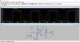
I've put a zener and (back diode) to mimic the breakdown of the JFET. As you can see over 5ma flows through at 40v which will quickly destroy it. Mooly I put a .asc in a previous post if you want the try this. So the design I think is flawed, and I would personally make changes to stop this happening again. I would also speak to the guys selling the unit.
JFETs are resonably ESD tolerant its MOSFETS you have to watch.
Last edited:
Well the iron I picked up was at 375, and talking to a friend he was expecting the iron to take say 3-10s or more to melt the solder, and this is taking 2-3 tops? Just don't want to spoil the board tracks //
Mooly I put a .asc in a previous post if you want the try this. So the design I think is flawed, and I would personally make changes to stop this happening again. I would also speak to the guys selling the unit.
Thanks... the .asc called 'buf'?
🙂
I tried it quickly on my sim and agree that under certain conditions (very high signal levels) you could exceed the FET's breakdown voltage... so it isn;t a great aspect of the design I suspect.
Well the iron I picked up was at 375, and talking to a friend he was expecting the iron to take say 3-10s or more to melt the solder, and this is taking 2-3 tops? Just don't want to spoil the board tracks //
Once up to temperature the iron and tip should be suitably sized so that the solder melts pretty much instantly. I use a Philips temperature controlled station and usually work at 300C or even a little lower.
Attachments
I am using lead and some silver in an RS Pro solder. Iron is at 375, so maybe I should drop it a little?
baudouin0 - this is the design details for the unit, the version I have is revision E and it's got the FETs whereas the earlier versions of the sp8 were actually diodes. It's also around 1983 manufacture, so an old and a little tired unit, but it just sounds good. last 4 pages show the circuit https://www.arcdb.ws/Database/SP8/ARC_SP8_manual.pdf
375C sounds to hot to me... the solder should melt cleanly and flow well but if its to hot then flux will just burn straight off... you'll know when you see it do that.
If the solder is flaky or crusty then the iron isn't hot enough. As I say, I find around 300 or lower ideal.
If the solder is flaky or crusty then the iron isn't hot enough. As I say, I find around 300 or lower ideal.
Yep the collapse of negative feedback makes the problem rather worse driving V5 into hard conduction.
Thanks - I'll try it at 300 and see how it works out, I have been using it at 375, but did wonder it it was a little hot 🙂
I would just practise on an old PCB until you have the hang of it. If its silver solder you do need it quite hot.
ok - so now I really need some help!!
The LH channel is now quiet on hiss with it's new 5462 carefully soldered in place. The RH channel now plays absolutely nothing through it. All I have done is remove and replace the FET. I have measured voltages and they all look great on the v4, v5 anodes.
Where would you start and any ideas I am lost and annoyed with myself, as i must have done something really stupid somewhere.
So the FET has fixed the hiss... excellent 🙂 and what was the good channel is now now faulty... the joys of fault finding.
First thing is to be 100% sure the DC conditions are all correct so you need to include V6 cathode in those results.
Make sure you haven't isolated any parts and forgotten about them (such as coupling caps).
First thing is to be 100% sure the DC conditions are all correct so you need to include V6 cathode in those results.
Make sure you haven't isolated any parts and forgotten about them (such as coupling caps).
I was so happy for a few moments.....and now I wanted to let my brain absorb the possibilities before rushing in...and walk the dog!!
Fault finding is actually really interesting so don't automatically view it as a problem.
You know it all worked before... and if all you have done is replace a FET on that channel then that has to be the first thing to look at.
Check continuity from each leg to where it should go. Make sure you read 1k between anode of V5 and the grid of V6
You know it all worked before... and if all you have done is replace a FET on that channel then that has to be the first thing to look at.
Check continuity from each leg to where it should go. Make sure you read 1k between anode of V5 and the grid of V6
well it seems it's not the preamp.....it's my old DAC going down on the RH channel....it did do this before a while back and I though it was the leads...then it came back again and I had forgotten all about it until now. Shame as I think it's going to sound great.
I will probably swap out the the RH FET to the right spec too as this side has a bit more fuzz/hum and I hope this might be to blame 🙂
I will probably swap out the the RH FET to the right spec too as this side has a bit more fuzz/hum and I hope this might be to blame 🙂
yeah unfortunately....it is a little old and out of date (an early DacMagic) I have tried 3 other way more expensive DACs from friends, but this one still makes more music to my ears than any others I have had at home (and to the ears of those who have brought round the 'better' dac)
Maybe just the RCA connector on the dacMagic output or if its PCB mount a dry joint where is been inserted too many times.
ok - well it was my bad, one of the RCA cables was broken on the signal joint. I am using Duelund cables and had not made a big effort to make them durable to lots of wiggling....now re-soldered.
AND no annoying in appropriate hiss, it is an all valve system with horn speakers so I can't expect total quiet. Small hum left but that's a future project to play with, something weird going on with on with the heater wires on V4 I think.....
The removal of the optocoupler is permanent now as it sounds so much better that way
THANK YOU VERY MUCH baudouin0 & Mooly I absolutely could not have done this alone!! Where are you in the country, I am based in West Sussex
- Home
- Amplifiers
- Tubes / Valves
- Hiss on 1 channel ideas