A 2N5460 or 2N5462 on some Ohm meters may very well measure 250 Ohms from Source to Drain. With the Gate at zero volts versus the source/drain, the JFET is in the Ohmic region, it is not in the constant current region.
Read the Ohms from the Gate to the Source/Drain.
Then reverse the Ohmmeter leads, Source/Drain to the Gate.
One is forward conduction, should be low Ohms.
The other direction (reverse) better be extremely high resistance.
(Please make me stop thinking about a JFET, it hurts my head, it is only adjusted to vacuum tubes; just kidding).
Could you measure the voltage on cathode of V4 with fet removed just to check there are no other damaged components,
So a lot of posts since last night 🙂
The hum you have sounds a bit unrelated but lets just see how it all pans out with replacement FET's.
My understanding of the circuit (and the last valve I touched was probably something like a PL509 in a CTV back in the 80's 😱) is that the circuit should all operate absolutely normally without those FET's in place, start up and switch off states excepted.
Anyhow 🙂
If V5 conducts hard and C10 is charged and connected to say 4k7 load that would put more than 40v across the FET. Maybe a JFET (for low leakege) and a 1n4148 (for reverse voltage) in series would do the trick.
Last edited:
plus reconnecting the LH 5460FET (I have not disconnected or touched the RH 5460 one yet) also immediately dropped the resistance measured across the 300k LH anode resistor on V5 to 140k, and this returned to 300k on removal of LH FET again.
A lot of interpretation is needed in cases like that.
When semiconductors are involved the polarity of your meter test leads can make a big difference when measuring in circuit resistances. Also any slight residual voltage between points can confuse the reading. This is why parts like resistors have to be isolated to get an accurate determination.
If the resistors read correct when isolated and out of circuit then refit them and forget them and concentrate on careful voltage measurement.
All measure FET out of circuit on LH
12.7 V on pin 8 cathode of V4
FET 220R on way and 191R the other way
measuring pin 3 V4 difficult due to access, but think its likely 18V or so
12.7 V on pin 8 cathode of V4
FET 220R on way and 191R the other way
measuring pin 3 V4 difficult due to access, but think its likely 18V or so
You can not measure a JFET with the Gate floating (un-connected).
Ohmmeter tests:
('Reverse leads' means reverse Ohmmeter leads)
Short Gate to Source.
Measure Source to Drain.
Reverse leads, measure Drain to Source.
Depending on your Ohmmeter, this will be either in the Ohmic region, or in the constant current region (IDSS).
Short Gate to Drain.
Measure Source to Drain.
Reverse leads, measure Drain to Source.
Depending on your Ohmmeter, this will be either in the Ohmic region, or in the constant current region (IDSS).
Let the Drain float (un-connected).
Measure Gate to Source.
Reverse leads, measure Source to Gate.
One of these Must measure Very high resistance.
The other is the forward conduction of the Gate, about 0.6V.
Let the Source float (un-connected).
Measure Gate to Drain.
Reverse leads, measure Drain to Gate.
One of these Must measure Very high resistance.
The other is the forward conduction of the Gate, about 0.6V.
Last edited:
The FET (faulty one) may well behave differently under dynamic conditions compared to just a simple resistance check on a meter which uses a low test voltage.
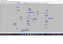
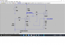
I've just had a play around with that stage as a simulation and this is the result. You can see that the FET itself makes no difference to the DC voltages when operating normally.
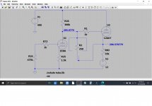
If we place a resistor across the FET then the voltages obviously change as shown.
The valves used are the closest I could guess at for a sim and the the exact types used do make quite a difference to the voltages although the voltaages all track 'in proportion' with different devices.
Edit... that's better. First image was wrong, I changed the sim but didn't re-run. All good now.
So with, without and with resistor:
I've just had a play around with that stage as a simulation and this is the result. You can see that the FET itself makes no difference to the DC voltages when operating normally.
If we place a resistor across the FET then the voltages obviously change as shown.
The valves used are the closest I could guess at for a sim and the the exact types used do make quite a difference to the voltages although the voltaages all track 'in proportion' with different devices.
Edit... that's better. First image was wrong, I changed the sim but didn't re-run. All good now.
So with, without and with resistor:
Attachments
Mooly,
You posted before I was done re-editing my Post # 68 that only partly preceded your post.
You posted before I was done re-editing my Post # 68 that only partly preceded your post.
I can't see what you're doing until you actually post it 🙂
...and the timeline is set by the original posting time. No one can alter that, its cast in stone. Deleting my post to give a correct version was legitimate and any standard user could do the same within the edit window. It was quicker than deleting the images and reinserting them to preserve the order.
Now you've posted I can see you edited yours four times... which is fine 🙂
Mooly this is really GREAT! so my hopes are really up to swap the FETs to 5462 and get a stable amp....hopefully with less hiss 🙂
 well lets hope so.
View attachment buf.asc
Ok so with the output mute relay shorted and a large signal driving the JFET can end up with 150V of reverse voltage. The plots are the grid and the cathode of the ECC88. This is almost certainly the reason why they blow. Maybe audio research should be made aware of the issue.
I would replace the JFET with something like a 1n485b low leakage 200V and a series 10k resistor. I notice their previous schematic was using 1n914 rather than the jfet.
Last edited:
Mooly, if this works I think you might have earned a bottle of something 🙂
Lol, thanks for the kind words 🙂
baudouin0, thanks for some diligent work on my behalf!! I am going to try the standard fit 2N5462 on the LH channel and see how the circuit stabilises, and then try some signal through for both music, and confirming the level of hiss. Should I determine from your note that the mute circuit should be left open on start up to help prevent damage, turning the power amp on after a few minutes, or can I still power up with mute in place?
Thanks so much!
Thanks so much!
one more question for the more experienced, what temperature should I set the soldering iron at for the removal and re-soldering of the FETs etc? I have borrowed a controllable iron for this work.
Thanks!
Thanks!
Make sure it's ESD safe... Mine said it was but wasn't. It would blow up any FET I tried to solder because it had 40V on it.
As far as temperature, the datasheet will tell you... Personally, I use 380c even if it's hotter than the max spec on the datasheet, I've never damaged a part with soldering heat.
As far as temperature, the datasheet will tell you... Personally, I use 380c even if it's hotter than the max spec on the datasheet, I've never damaged a part with soldering heat.
- Home
- Amplifiers
- Tubes / Valves
- Hiss on 1 channel ideas