If the FET goes short then the cathode of the cathode follower will just keep pushing up the grid which is what you see. Remove and replace with 1n914/1n4148 and 10k in series. Diode should be revered biased in normal operation. It protects the cathode follower during warm up. Check the cathode follower resistor too as it might have got hot.
Last edited:
Mooly, thanks again I picked up your note after I had already posted my last.
so the plan is I will remove FET on LH channel again, put in V6 and power up and test voltages? The part that confuses is me is what I do with the capacitors C10 and C43 in this trial as I am not sure what isolating these actually means - just disconnect on one end?
If I do this then how do I get output across to R29/
Yes, try with the FET's removed. Isolating does mean either just lifting or unsoldering just one end of each so that it is electrically out of circuit. Often easier than actually fully removing a part.
All we are trying to do at this stage is to get the DC conditions correct and so there will be no audio output.
The devil is in the detail here... do you mean you put the FET leg back on both channels or just one channel.ok - so I put the leg of the FET back and the 350V V5 anode came back, as did the 140K across V5 anode resistor on LH. Also the RH voltages went back into shape.
Any ideas ?!?!
There should be no interaction between channels, a fault on one should not affect the other (other than things common to both such as supplies or valve heaters etc)
Ok - so I have put in V6, removed FET again on LH channel and powered on.
180v V4 RH 300K across anode resistor (socket 1)
180v V5 RH 300K across anode resistor (socket 6)
180v V4 LH 301K across anode resistor (socket 6)
160v V5 LH 300k across anode resistor (socket 1)
cathode LH 175, RH 185
listening LH much less hiss, nut now a lot more hum, did not play any music.
180v V4 RH 300K across anode resistor (socket 1)
180v V5 RH 300K across anode resistor (socket 6)
180v V4 LH 301K across anode resistor (socket 6)
160v V5 LH 300k across anode resistor (socket 1)
cathode LH 175, RH 185
listening LH much less hiss, nut now a lot more hum, did not play any music.
not sure how stable the voltages are supposed to be - the 400v input is very stable, these voltages oscillate a little.
Check R27, R28 and R83. The much higher voltage during the fault could possibly affect the values due to heat. R83 could be open. Cathode LH should not be more than 7v above V5 LH. You will need to replace the JET to prevent possible damage to the cathode follower valve during warm up. A diode + 10k will do - but if you go with a JFET I would put a resistor in series with the gate of the FET (4k7) to prevent it from being blown up again.
Last edited:
Ok - so I have put in V6, removed FET again on LH channel and powered on.
180v V4 RH 300K across anode resistor (socket 1)
180v V5 RH 300K across anode resistor (socket 6)
180v V4 LH 301K across anode resistor (socket 6)
160v V5 LH 300k across anode resistor (socket 1)
cathode LH 175, RH 185
listening LH much less hiss, nut now a lot more hum, did not play any music.
So all those voltages look more as they should be.
Those cathode voltages are V6 I assume ?
Are the caps removed? If so then its not really a valid test to listen to the output because it is effectively floating and so will pick up hum and noise.
If they are removed then you can refit the caps and recheck the DC voltages and then listen to music if all is still OK and see how it performs.
Have to leave it for tonight but hopefully we are making progress.
Mooly,
Thanks so much.
Yes those are cathode voltages with LH FET disconnected, on V6
So my take on this based only really on logic is that the 2N5460 FET that was replaced that is acting as a diode is under rated, and should have been 2N5462 as was originally supplied and specified. I am going to pick some of these 2N5462s up tomorrow, so I might drop one in and see, taking out the old 2N5460 completely and putting 5462 in.
The hum and hiss I heard were with the capacitors still in circuit.
I hope the hum drops back to a 'normal' level when I put the correct spec FET in circuit, AND the hiss is lowered as what was heard was this faulty FET....
that would make me super happy 🙂
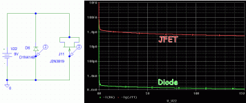
No idea why they are using a FET as a junction diode.
Lower leakage current.
1N914 et al are doped for good conduction and low (not ultra-low) leakage.
The ONLY point of a JFET (for many users) is that SUPER-low input current, so they dope for low-low-low current.
The JFET diode was well-known to 1990s sample/hold builders.
Whether it may be good or bad here, I can't say. Thousands of amps have been built without grid protection, and many serve well. However the tube used here is one of the more sensitive. We could also wonder if the low-low back current is needed here, if a 1N914/4148 could really be heard. Not by me, but by somebody?
Attachments
Last edited:
That's interesting I did not know that. I guess at higher temperatures the leakage could affect the grid voltage and the distortion of the circuit hence the use of a JFET. The fact two FET have gone in the circuit must indicate at some stage the current in the gate exceeded 10ma. I guess this could be an small arc between plate and grid of the cathode follower at switch on. The missing FET does not affect normal circuit operation. If the cathode resistor has gone up in value this will affect both the cathode grid voltage of the follower and also increase the stage gain due to lack of NF which may explain the increase in hum/noise. Check the voltage on V4 cathode - that's a good check the resistors are OK. The wrong voltage here will not affect V4 plate due to the way the grid is biased.
Last edited:
Before any tube warms up, the 300k RL of the second tube drives B+ through the JFET, to the cathode of the 6DJ8. The Cathode is returned by 3 more resistors in series, a 33k, and 2.7k in parallel with 6.78k, to ground.
If B+ comes up before the second tube conducts, the forward Gate current might exceed its safe level.
A Pico-amp JFET gate is very sensitive.
Check out the safe gate current for that exact JFET type.
I bet pico-amp JFET gates are Very sensitive to static charges.
If B+ comes up before the second tube conducts, the forward Gate current might exceed its safe level.
A Pico-amp JFET gate is very sensitive.
Check out the safe gate current for that exact JFET type.
I bet pico-amp JFET gates are Very sensitive to static charges.
Last edited:
my first repair guy I THINK did a swap and try approach (including the 4 FETS) and could not fix a loud hum (or more likely ran out of patience with my amp) the second repair guy sorted the hum that was still there from the first but not the hiss (re dressed a cable and swapped out yet another valve). Hence I though it time to just try and resolve myself......(well actually with all of this great help)
I had to swap out the old mains transformer as this both mechanically and sonically hummed a lot. If anyone wants a recommendation for a transformer company then let me know. I had this one built for me to match the SP8 spec and all the voltages are spot on, and it definitely sounds better than the original in my view (more vivid and dynamic) BUT the original was over supplying voltages. It was less than £100 from memory and ARC wanted £600 or so....
Thanks everyone, I am learning lots!!
Well the 2N5462 is rated for 10mA forward gate current,
But it is only rated for 40V in reverse.
Is there anything that the circuit can do to exceed the 40V reverse?
Either in the case of the circuit working properly?
Perhaps a power on transient.
Or in the case of the circuit working im-properly?
But it is only rated for 40V in reverse.
Is there anything that the circuit can do to exceed the 40V reverse?
Either in the case of the circuit working properly?
Perhaps a power on transient.
Or in the case of the circuit working im-properly?
Yep could not see why it would exceed 10ma other than an arc to the grid and dumping the 400V or so across the 33k. The FET would only be damaged if the reverse voltage also had current. I wondered if a series resistor would help if that's the problem, Wondered if this could happen if the stage is over driven.
I always switch on the amp with mute selected, and I have no optocouplers since the attempt to find these as culprits, so I could power on with or without mute, but I would not turn on the power amp until the sp8 was on for 3 mins or so. Oh btw with optocouplers out it definitely sounds better (but this could also be the different 511ohm resistor I suppose)
If there is Reverse Current that causes gate to source/drain to exceed 40V, the current times the voltage might damage the gate.
10mA
Forward conduction:
0.6V x 10mA = 6mW in the gate
1mA
Reverse conduction:
40V x 1 mA = 40mW.
40mW will not destroy a JFET Channel (Source to Drain).
But 40mW Might destroy a gate.
Has it been determined for sure that the JFETs were destroyed, or not?
Both the gate current, and the reverse voltage ratings, of the 2N5460 and the 2N5462 are the same.
Last edited:
Yep if the output is loaded and the stage is over driven the grid of the cathode follower could be drive very negative wrt to cathode and put more than 40v across the JFET. The NF will make matters worse here. I think you said the JFET was reading 250R so destroyed. Think I would be placing a 10k in series with the gate of the FET.
Last edited:
plus reconnecting the LH 5460FET (I have not disconnected or touched the RH 5460 one yet) also immediately dropped the resistance measured across the 300k LH anode resistor on V5 to 140k, and this returned to 300k on removal of LH FET again.
- Home
- Amplifiers
- Tubes / Valves
- Hiss on 1 channel ideas