Hi,
Here's my monster PCB finished yesterday- thanks for nice layout to PCB designer from this thread! ( without all transistors, corresponding resistors and the pot, because I do not know what will be the transistors BL or GR type or alternative Jfets and outputs also installed just for PCB fitting test- still waiting for original transistors instead of TIPs ).
PSU planned to be + - 12V Pass-style CRC filter with approximately 40000uf 0.1R and another 40 000uf per rail. transformer will be 200VA with fast diodes and i plan to add soft start - thermistor or relay with power resistors. Still need to solder Fuse holders on PSU board and add some snubber capacitor across diodes.
hello,
Today I got the ISC 844 and 754 output transistors. Visually it looks good. But how is their quality? Does anyone have them use your monster or Is it better to stick to the TIP pairs?
thank you!
regards,
Oskars
Today I got the ISC 844 and 754 output transistors. Visually it looks good. But how is their quality? Does anyone have them use your monster or Is it better to stick to the TIP pairs?
thank you!
regards,
Oskars
Hi,
Here's my monster PCB finished yesterday- thanks for nice layout to PCB designer from this thread! ( without all transistors, corresponding resistors and the pot, because I do not know what will be the transistors BL or GR type or alternative Jfets and outputs also installed just for PCB fitting test- still waiting for original transistors instead of TIPs ).
PSU planned to be + - 12V Pass-style CRC filter with approximately 40000uf 0.1R and another 40 000uf per rail. transformer will be 200VA with fast diodes and i plan to add soft start - thermistor or relay with power resistors. Still need to solder Fuse holders on PSU board and add some snubber capacitor across diodes.
It seems another monster is being born!
a note here, you use wire resistors for the power transistors which have much inductance. Look at my version here Le monstre which uses metal resistors. I have many of them matched and available if you are interested you may contact me at skylimit000 AT gmail.com
Yesterday I reversed the input fets and started to convert the PSU coaxial plugs that I used (BNC not banana ones) in order the supply lines to use the external conductors which are thicker. Note I have not put these two conversions on the website yet.
Currently I more worried about the choice of output transistors. JFET will be used 170/74 GR.
Thanks for the resistors offer - i will think about it.
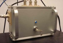
here photo of transistors and the new enclosure 😉.


If I understand correctly, these transistors are not fakes, but a copy of original but i have doubts about quality .
Thanks for the resistors offer - i will think about it.
here photo of transistors and the new enclosure 😉.
If I understand correctly, these transistors are not fakes, but a copy of original but i have doubts about quality .
Does the capacitors (47uF) on the amplifier PCB make any difference if placed with greater capacitance?
Does the capacitors (47uF) on the amplifier PCB make any difference if placed with greater capacitance?
Yes, There is a discussion about this in an earlier post. I have put a total of 4700uF in parallel with 0.47uF teflon cap in mine. The PSU has huge of capacitance anyway so I do not know if the value on the PCB matters. I have the battery only PSU that is why I have put greated capacitance here.
Currently I more worried about the choice of output transistors. JFET will be used 170/74 GR.
Thanks for the resistors offer - i will think about it.
here photo of transistors and the new enclosure 😉.
If I understand correctly, these transistors are not fakes, but a copy of original but i have doubts about quality .
Where did you get this box?
I had a hard time making the homemade box!
Hi,
Those boxes look ok, but I didn't find any company information from that page? Address, nothing..
- Elias
Those boxes look ok, but I didn't find any company information from that page? Address, nothing..
- Elias
Hi, box from modu,
Hello
With 200VA transformer it will be OK.
You will lose 2-3V when loaded may be 4V , don't forget it is a Class A amp! Depend on the bias how high you set it up...
I used 300VA transformer and it was warm my transformer.
The amp bias was over 1A in cold, after1 hour or so 1.2 - 1.3A/ channel..
Greetings
Last edited:
Thanks, I hope so, i will try to load it tomorrow - i still need to get 100R and 220R trim pots for tests - 470R i have but it seems for me to big for GR grade Jfets. I think that the higher voltage as usual -due low voltage drop diodes in rectifier.😕 With standard bridge voltage is lower.
I like this company! they accept paypal too. the REAL good ones have 250Euros, this is too much! but the smaller ones are wuite affordable
Yes, in my country it is difficult to find a suitable radiators for class A.
So count aluminum radiator prices + Aluminum and auux.materials (drills, sanding paper etc)- just over 100EUR.
This time I decided to buy 😀
Shipping was very fast, but I forgot to order a perforated chassis ...another option - par-metal.com cases from ebay, but delivery to Europe more expensive.
So count aluminum radiator prices + Aluminum and auux.materials (drills, sanding paper etc)- just over 100EUR.
This time I decided to buy 😀
Shipping was very fast, but I forgot to order a perforated chassis ...another option - par-metal.com cases from ebay, but delivery to Europe more expensive.
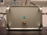
I feel like it is time to post some updated photos of mine.
Amplifier was setup on 500mW drom and a little bit more when heated
Is it class-A or is it too low that drops into AB??
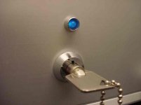
Here are the photos with my homemade box too. The LED is silicon carbide and yes it is dim 😉
The I/O connections (male ones) are not good yet
Amplifier was setup on 500mW drom and a little bit more when heated
Is it class-A or is it too low that drops into AB??
Here are the photos with my homemade box too. The LED is silicon carbide and yes it is dim 😉
The I/O connections (male ones) are not good yet
Attachments
Hello guys, i made hiraga with 12 volt and using original components only i using BL grade for jfets with 390 ohm resistor instead 1k ohm. do we have to match every transistor? i never have matched transistor and my le monstre reach over 1 ampere bias and i need to reduce because i have no good heatsinks. what should i do to reduce? should i change the jeft to 2SK246 GR or reduce the 390 ohm resistor? Any suggestions? thank you guys.
Hello guys, i made hiraga with 12 volt and using original components only i using BL grade for jfets with 390 ohm resistor instead 1k ohm. do we have to match every transistor? i never have matched transistor and my le monstre reach over 1 ampere bias and i need to reduce because i have no good heatsinks. what should i do to reduce? should i change the jeft to 2SK246 GR or reduce the 390 ohm resistor? Any suggestions? thank you guys.
As previously suggested you only have to alter the 1K restistor at the base of the driver transistors to adjust the bias. See here for the alignment process I did. Le monstre
Tonight I launched monster in test mode :

ISC outputs, GR grade Jfets - still don't have pot , so i use 2x 100R and 1K for bias - its around 0.4Amps.

square wave 20Khz

clipping
About monster sound- don't know yet, but if there is such osciologram, I suppose that sounds 😛
ISC outputs, GR grade Jfets - still don't have pot , so i use 2x 100R and 1K for bias - its around 0.4Amps.
square wave 20Khz
clipping
About monster sound- don't know yet, but if there is such osciologram, I suppose that sounds 😛
Did I get it right???
I read through it, and extracted the following advise:
1. Get original transistors
2. Use 100 Ohm trimpot
3. For JFets use V type not GR or BL, because V is replacement for Y
4. If Current in output Stage does not fit, change resistors on the collectors of cascode transistors
5. Desired outpot stage current is 800mA (for original design)
Open question: Which board should I take???
The one used at:
Audio Constructions
Which is the size of the PCB (If I have to print, I need the scale factor...)
Regs, Dirk
Hi,
You can find in this thread PCB pdf file and print it at 1:1. Do not forget to turn around the FETs. PCB size was 5x6 cm if i not mistaken. I made a little bigger size from one side to have a place 4 screws. You can also use other transistors, only then you will need to experiment with cascode resistors and pot ..Bias approx around 0,5-0.6A if i understood correctly.
You can find in this thread PCB pdf file and print it at 1:1. Do not forget to turn around the FETs. PCB size was 5x6 cm if i not mistaken. I made a little bigger size from one side to have a place 4 screws. You can also use other transistors, only then you will need to experiment with cascode resistors and pot ..Bias approx around 0,5-0.6A if i understood correctly.
- Home
- Amplifiers
- Solid State
- Hiraga "Le Monstre"