I don't know your scope, but you'll need one with a certain bandwith (I suggest at least 20 MHz). DMM is not of much help.[...]can i use my scope or DMM to check if it's oscillating?[...]
Then you need a signal generator, or you can use your soundcard with REW.
Drive your amp at different levels, with sine and square wave signals, with resistive and real loudspeaker loads. If the output shows other waveforms than the input (overshoots, high frequency content, ...), that is not good and shows that the amp is not stable enough. Do a Google search on "Amplifier Oscillation" and look at the pictures in the search results....
Sanken and OnSemi are pretty much state of the art. You may also try 2SC5200 and it's PNP counterpart from Toshiba, an excellent transistor.[...]The thing is i don't just want "ok" transistors, i want proven and tested transistors that perform well with this circuit that others have recognised.
You need constant (high) hfe at higher currents, a fast transistor, cob as low as avialable.
There is no such thing as a "wonder-transistor", and the difference between those suggested is overrated in my opinion.
How much the DC offset?
Of course, you set up the DC offset at industrial warm.
I had the same issue with my LeMonstre, even the bias moved at warm up.
If you have 1V DC at cold that is not a problem as long as your speaker's protection does not kick in.
Is not possible to put together your heatsinks to create some type of tunnel for your fan, that way would be much more effective. You can buy 5W metal film resistors and carbon films also.
I would buy 2R and use 2PC to get 1R 10W. Did you ever tried plate resistors like KOA etc. to me those acceptable also.
Ok so at first switch on the dc offset was:
The sankens were 919ma and the MJL's 418ma.
Stuck a timer on and after 35mins the temp was 41 degrees Sankens went down 30ma and the MJL's 35ma
It took almost an hour for both of them to get to 0V. at which point the temp was around 46degrees.
after two hours both heatsinks averaged about 47-48 degrees.
So yes it shows that dc offset is proportional to the temperature raise.
One more question do both transistors have to have equal levels of bias? For me to have it stable its like 0.60 on the npn and 0.62 on the pnp.
Last edited:
I don't know your scope, but you'll need one with a certain bandwith (I suggest at least 20 MHz). DMM is not of much help.
I have a velleman hps140mk2:
Specifications
bandwidth: up to 10 MHz (-3dB or -4dB at selected ranges)
input range: 1 mV to 20 V / division in 14 steps
input coupling: DC, AC and GND
real-time sample rate up to 40 MS/s
AD resolution: 8 bits
time base: 250 ns to 1 h per division
auto set-up function (or manual)
probe x10 readout option
readouts: DC, AC + DC,True RMS, dBm, Vpp, Min-Max. (±2.5%)
audio power measurement from 2 to 32 ohms
hold & store function
time and voltage markers readout
max. 100 Vp AC + DC
Monochrome OLED
power supply: 4 x 1.5 V AAA batteries (not incl.)
operating time: up to 8 hours on quality Alkaline batteries
for use on CLASS II pollution degree II installations
dimensions: 114 x 68 x 22 mm
weight: 166 gr
current consumption: max. 150 mA
Then you need a signal generator, or you can use your soundcard with REW.
I have both!
Drive your amp at different levels, with sine and square wave signals, with resistive and real loudspeaker loads. If the output shows other waveforms than the input (overshoots, high frequency content, ...), that is not good and shows that the amp is not stable enough. Do a Google search on "Amplifier Oscillation" and look at the pictures in the search results....
Ok sounds easy enough, ill do a quick search and see how to go about it
Sanken and OnSemi are pretty much state of the art. You may also try 2SC5200 and it's PNP counterpart from Toshiba, an excellent transistor.
Excellent ill order some
You need constant (high) hfe at higher currents, a fast transistor, cob as low as avialable.
There is no such thing as a "wonder-transistor", and the difference between those suggested is overrated in my opinion.
not looking for a wonder transistor just ones that other members use and enjoy so at least i can try and choose what i like.


I tell you what you guys, this made such a difference. It felt so much easier to set the bias and dc offset up, infact i was able to get both NPN and PNP to match in bias.
Cant believe the difference changing the type of resistor made.
I would suggest you to try these Power transistors also NJW0281G and NJW0305G. I am using them in my 30 WATT Jean Hiraga schematic by Dan. And they are sounding very beautiful.,,
Thanks Sadik I just ordered those transistors again as I blew my last ones fiddling and learning, agreed they did sound lovely.

What a good day it was for testing, i was really able to put these amplifiers through their paces and they did not disappoint.
Ill keep it quick and simple.
Preamps:
Yamaha ca-600 (i like the mode function where it joins the Left and Right signals together so the preamp outputs share both signals) . This allowed me to test one amplifier at a time but getting both L/R signals coming through.
Diy Marantz 7 circuit Tube Preamp
Speakers:
Planet 10 onkens with MA alpair 7.3
Tannoy Berkeleys (i was very surprised how good it sounded with these amps)
Things really came alive when i used the big tannoys it gave a good impression of how well the amp performed and how the transistors used sounded.
Amplifer 1:
The MJL21193+MJL21194
Amplifer 2:
NJW0302G+NJW0281G
Both Amps were tested at 0.6A and 0.7A, allowed to be fully warmed and stable, i didn't want let the rail voltages drop below 16V. I will may 1A just to listen and test more, my thought was to eventually try and get a stable bias where my PSU you can handle the load and i get good measurements from my scope. I mean i tried 1.5A and it sounded strong, further tests showed no benefits cons were HEAT,PSU having a hard time and bad rms value tests from my scope. Just using 0.6 - 1A tests better for my current setup which is fine.
Ok i will continue this tomorrow as it's late!
Last edited:
Hi Vishal,
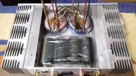
You may have seen the below photo of my amp (Jean Hiraga 30 Watts) It was a complete DIY right from the PCB's to the Enclosure.

But Now as the time has passed I too have updated my amplifier with Proper PCB's, Power Bank (4,40,000 uf Per Channel) and a Heavy Enclosure (Enclosure is a complete DIY) with More bigger Heat sinks. The Amp PCB's were made as per my layout from a PCB manufacturing company, Soft turn on & Protection PCB's were purchased as a complete assembled kits.
When i shifted to Proper power Bank there was a huge difference in the low frequency. The difference is on the better side, the low frequency is improved a lot the difference is like day & night.
When I was using Cap multiplier the lower notes were blurred and the intensity was very light. (but still it sounded very good in mids and high region)


Belive me this 30 Watter is a Real Monster. And so dose it looks now.
Sadik
You may have seen the below photo of my amp (Jean Hiraga 30 Watts) It was a complete DIY right from the PCB's to the Enclosure.
But Now as the time has passed I too have updated my amplifier with Proper PCB's, Power Bank (4,40,000 uf Per Channel) and a Heavy Enclosure (Enclosure is a complete DIY) with More bigger Heat sinks. The Amp PCB's were made as per my layout from a PCB manufacturing company, Soft turn on & Protection PCB's were purchased as a complete assembled kits.
When i shifted to Proper power Bank there was a huge difference in the low frequency. The difference is on the better side, the low frequency is improved a lot the difference is like day & night.
When I was using Cap multiplier the lower notes were blurred and the intensity was very light. (but still it sounded very good in mids and high region)
Belive me this 30 Watter is a Real Monster. And so dose it looks now.
Sadik
Sadik that is wonderful man, i like how you also had the metal work etched something i would like to get done on future projects.
I am in the process myself of finishing my Hiraga Super 30w using Chokes and a big PSU, although i decided to build the le monstre as a test run!
I am in the process myself of finishing my Hiraga Super 30w using Chokes and a big PSU, although i decided to build the le monstre as a test run!

is that better?
no!, not at all.
your earlier one is better.
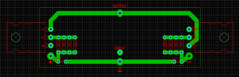
I only said , All input section grounds should meet at a single point, e.g. input signal -, FB ground, i/p section 47k res gnd, R6/R7 gnd, etc.
Last edited:
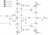
I will do this scheme
That is the modified version of the Hiraga class A.
I am not a fan of the 13V diode on the front, that version.
I built that and never like her at all.
Much more the 20V Zener D type.
Keep all the resistor values, the rail voltage can be lowered, only because I am not sure the type of heatsink you got will take the heat.
May be use 15 or 16VAC transformers.
Attachments

Last edited:
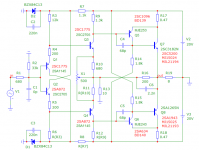
Many years ago (30?) I modified the Hiraga Le Monstre schematic and built a 25 W amplifier. After having moved around a couple of times, I replaced the amplifier with new ones.
Now I have started to go back to this amplifier, following the attached schematic, but not using the pair C2922 and A1216 (I don't remember which drivers I used). I used a 2x18 V tranformer with CRC-filtering giving plus/minus 24 V (no huge power supply).
Have someone tried something like this?
Now I have started to go back to this amplifier, following the attached schematic, but not using the pair C2922 and A1216 (I don't remember which drivers I used). I used a 2x18 V tranformer with CRC-filtering giving plus/minus 24 V (no huge power supply).
Have someone tried something like this?
Attachments
Last edited:
Some findings regarding the JFETs used in "Le Monstre":
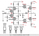
The original design uses the JFETs 2SK170Y/2SJ74Y which yield a current of approximately 1.3 mA in the input stage. The voltage drop across the 1 kOhm resistor is 1.3 V and the quiescent current in the output stage becomes 0.6 A. That's the original design and it is simply the best because it provides a substantial voltage gain of 7 in the input stage. Unfortunately these JFETs with IDSS classification Y are almost impossible to get nowadays.
The JFETs 2SK170GR/2SJ74GR yield a current of approximately 2.5 mA in the input stage. In order to maintain the quiescent current of 0.6 A you have to reduce the 1 kOhm resistor to about 520 Ohm. The voltage gain in the input stage drops to 4 (-5 dB).
The new version using the JFETs 2SK246GR/2SJ103GR and a 470 Ohm trim-pot yields a current of approximately 2.7 mA in the input stage. For a quiescent current of 0.6 A a load resistor around 480 Ohm is appropriate. But there's a big problem with these JFETs. The forward transfer admittance is significantly lower and the voltage gain in the input stage only is 1 (-17 dB). Hence the new version clearly is inferior, a loss of 17 dB in open loop gain is way too much IMO.
Conclusion: Go for the original JFETs with the lowest IDSS you can find. They are unrivaled in terms of gain and low noise. They now are produced under the new name 2SJ108 and 2SK370.
- Home
- Amplifiers
- Solid State
- Hiraga "Le Monstre"