It may have a hfe value higher than the adjustment range of the pot, you may need to alter the bias lower first. But you could have an issue at the front end of the circuit
Part of the issue is that you now have three trimpots, and all three can and will affect offset. Make sure the two trimpots replacing R2 and R3 are at a position where the bases of U5 and U7 (as per your schematic) are at about the same voltage differences from the respective rails (U5 to +rail, U7 to -rail), with Trimpot R1 at about in the middle position.
If you have done this, and still have high offset, a transistor is gone....
Smallish (+/-20%) differences of Hfe have not much to do with such a high offset.
Oh, and DO NOT attach your loudspeakers to such a high offset.
If you have done this, and still have high offset, a transistor is gone....
Smallish (+/-20%) differences of Hfe have not much to do with such a high offset.
Oh, and DO NOT attach your loudspeakers to such a high offset.
Last edited:
Part of the issue is that you now have three trimpots, and all three can and will affect offset. Make sure the two trimpots replacing R2 and R3 are at a position where the bases of U5 and U7 (as per your schematic) are at about the same voltage differences from the respective rails (U5 to +rail, U7 to -rail), with Trimpot R1 at about in the middle position.
If you have done this, and still have high offset, a transistor is gone....
Smallish (+/-20%) differences of Hfe have not much to do with such a high offset.
Oh, and DO NOT attach your loudspeakers to such a high offset.
For what it's worth I agree with sottomano, I forgot to add:
You should replace the bias trimpots with fixed esistors once you have the correct value
Thanks sottomano, i will check this later. When i use a multimeter as per these instructions:
Vetco Electronics Store near Seattle | Industrial and Maker Electronics for Less
to test the transistor which i know is gone and causing me problems, i use the diode function on the DMM the tests show that its ok? Which is bloody confusing, i know they are gone because if i resolder them to the amplifier board i get a high dc offset.
Right Dan, so once i am happy with my bias value, i simply remove the bias trim pots, measure there resistance value and replace them with fixed resistors.
Thanks sottomano, i will check this later. When i use a multimeter as per these instructions:
Vetco Electronics Store near Seattle | Industrial and Maker Electronics for Less
to test the transistor which i know is gone and causing me problems, i use the diode function on the DMM the tests show that its ok? Which is bloody confusing, i know they are gone because if i resolder them to the amplifier board i get a high dc offset.
Well, if the transistor measures correctly, chances are that it is not the (or that exact) transistor, but another reason.
Here another site who explains testing with a DMM:
Testing a Transistor with a Digital Multimeter - Engineering Tutorial
I just checked the datasheets of 2SB716 / 2SD756:
50mA is the absolute maximum rating for current.
They have to deliver the whole base current of "their" correspondent power transistor.
Depending on the hfe of the power transistor, this may be already too much, even more so as you seem to have shorted the output.
It could well be that a driiver is gone.
Yes and yes.
If you have a digital multimeter with the hfe function that will be the quickest way to check, you will need to de- solder the transistors to test them though.
-Dan
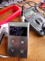
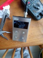
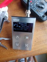
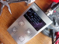
I have this component tester which connects to my scope. So i thought lets connect the trannies to it, now two of these trannies are supposedly gone as they give me a high dc offset.
Two of them work, two of them dont. i know this as i tested it on the boards,
These are njw21193G & 21194G
https://www.onsemi.com/pub/Collateral/NJW21193-D.PDF
Thing is the measure the same?!
Thanks sotto ill check those driver transistors out!
So which transistors do work? Each one PNP and one NPN?[...]now two of these trannies are supposedly gone as they give me a high dc offset.
Two of them work, two of them dont. i know this as i tested it on the boards,
These are njw21193G & 21194G
https://www.onsemi.com/pub/Collateral/NJW21193-D.PDF
Thing is the measure the same?!
[...]
Or two of the same polarity?
Looks like they are ok within the tolerance of the hfe from the datasheet?
Drivers to check next....
Drivers to check next....
Hi
I had one time a situation when I tested the transistor was right but under the load, on the PC board, it did not function properly. You can be sure a transistor works properly if you could test it under the same load as in the PC board. My advise if you burn an output transistor let say PNP change both of them! These for the power transistors only. The smaller (drivers) it does not work properly you can easily measure that with a simple DMM. Once you set up the bias with the two 1K trimmer you can use nail polish on the adjusting to glue that so it won't move while you play around with your PC boards. I hope this helps to get back your amp.
I had one time a situation when I tested the transistor was right but under the load, on the PC board, it did not function properly. You can be sure a transistor works properly if you could test it under the same load as in the PC board. My advise if you burn an output transistor let say PNP change both of them! These for the power transistors only. The smaller (drivers) it does not work properly you can easily measure that with a simple DMM. Once you set up the bias with the two 1K trimmer you can use nail polish on the adjusting to glue that so it won't move while you play around with your PC boards. I hope this helps to get back your amp.
sottomano i think as Garborbela suggests when the transistors are underload then thats when there are issues. They test fine on my DMM and on the component tester, but as soon as theres some load going into them they dont like it!
So i've learnt some things here, be careful not to short anything, if you suspect one transistor is gone change both of them.
I will check the drivers just incase. I've ordered some spare drivers as you never know!
So i've learnt some things here, be careful not to short anything, if you suspect one transistor is gone change both of them.
I will check the drivers just incase. I've ordered some spare drivers as you never know!
I agree with Gabor.
But, my question remains:
Which transistors do work when tested in circuit? One PNP and one NPN each, or two of the same polarity? If so, which ones?
But, my question remains:
Which transistors do work when tested in circuit? One PNP and one NPN each, or two of the same polarity? If so, which ones?
Well actually since they all measured the same i just changed them around until the circuit worked properly. So i cant really answer that sottomano. Just one working NPN and one PNP is all i know!

Finally came in the post, ordered from farnell so guaranteed these are not fakes!
One channel will be the sankens, the other will be the MJL's.

So handy to have these soldered on! Means i can switch between Trannies
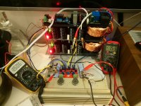
We are back in business!
Yes Dan i want to see the effects of using different transistors based on bias settings, power produced, how they sound etc.
Incidentally these sankens work much better on a lower bias, i had them at 0.6V and they performed better there then at 1.5A. My scope showed better results at 0.6v, i even had more power, can that be right?
Ill have to take pics of the results.
- Home
- Amplifiers
- Solid State
- Hiraga "Le Monstre"
