😍😍😍😍😍👏👏👏As I just stumbled over this thread: It is remarkable that people are still building this great amp after so many years! My first one was an order by some friends who needed a presentable build for an exhibition in 1984. It still lives and is operational ...
View attachment 1035209
After quite some time a pair with a somewhat reduced CRC supply ended as „drawer"-amp in a high efficiency speaker setup.
View attachment 1035213
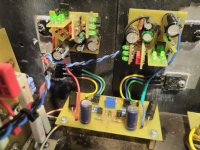
A stand-alone mono version ist also still in use, incorporating a budget CRC supply with a total of 120 caps with 4,700µF each.
View attachment 1035214
Each of these amps uses the original PCBs and Transistors, each is still a real pleasure to listen to!
I still have great difficulty in understanding the apparently widely accepted concept that more capacitance in an Hiraga amp's power supply will produce a better performance - is there some basis of reality to this excessive energy storage- it just doesn't make any sense at all and I wonder where it came from
Will an excessive number of "average type" capacitors substitute for a few high quality reasonable sized capacitors? Is there any specific quality of the capacitors that create a "better sound"? Does the Hiraga design require over a 100,000uF capacitance to function properly?
Will an excessive number of "average type" capacitors substitute for a few high quality reasonable sized capacitors? Is there any specific quality of the capacitors that create a "better sound"? Does the Hiraga design require over a 100,000uF capacitance to function properly?


Coz it sounds amazing! There is a difference, every component you add/remove will change the sound. The question is not "If" but "How".I still have great difficulty in understanding the apparently widely accepted concept that more capacitance in an Hiraga amp's power supply will produce a better performance - is there some basis of reality to this excessive energy storage- it just doesn't make any sense at all and I wonder where it came from
Will an excessive number of "average type" capacitors substitute for a few high quality reasonable sized capacitors? Is there any specific quality of the capacitors that create a "better sound"? Does the Hiraga design require over a 100,000uF capacitance to function properly?
And yes, there is no ceiling, but there may be "diminishing returns".
Personally I like the Le Monstre run around 17v with around .250F, that for me is the sweet spot. I have also found that it really likes the Nutube amp designed by our own Pa. It does not seem to like most trannies or other tube pre's I have thrown at it. The Nutube really suits it very well.
And as a side note, it seems to like the more complex speaker loads....
Last edited:
I once built a modified Monster (higher power supply voltage and higher bias with different transistors) with an added separate case for the most of the power supply, housing x number of 47000 uF capacitors (I don't remember the exact number). And the result? Compared to the smaller power supply of just six 47000 uF capacitors, I couldn't hear any large difference. The worst thing was, I found the smaller supply to make the amplifier sound better, hopefully this was pure imagination? But afterwords with my Hiraga-type amplifiers, I've been happy with the smaller power supplies.I still have great difficulty in understanding the apparently widely accepted concept that more capacitance in an Hiraga amp's power supply will produce a better performance - is there some basis of reality to this excessive energy storage- it just doesn't make any sense at all and I wonder where it came from
Will an excessive number of "average type" capacitors substitute for a few high quality reasonable sized capacitors? Is there any specific quality of the capacitors that create a "better sound"? Does the Hiraga design require over a 100,000uF capacitance to function properly?
Hello,
If you read the original publications by Jean Hiraga and the very few writings that have been published in France about " upgrading its power supply " you will know that 99% of currently build " le monstre " amps are different animals.
Maybe some might be better.
IF i would own the original one i would surely try to get one working with these so called supercaps. That is if i can make it with positive and negative supply voltage at identical numbers. I think that with this amp just like the Hiraga when both sides are not the same you will have dc at its output.
Greetings,Eduard
No, that is not the case, I had a slight difference in voltage due to different chokes. No startup bump with 10X56.000 uF. You set the DC manually of course. The differences in the resulting emitor resistance helps in the sound.I think that with this amp just like the Hiraga when both sides are not the same you will have dc at its output.
Greetings,Eduard
Hello,
I do remember that with the MC preamplifier Hiraga designed there was an extra resistor to kind of balance the current being drawn by the positive and the negative side of the circuit. This was also a supply that used batteries.
Sure there was a Cosmos trim potentiometer to set the DC close to zero.. But i think that if both sides dont draw identical current or if there some kind of difference between the batteries during discharge DC will change.
I remember reading the effect of using car batteries was big. It was described in NR36 L'Audiophile published autumn 1986. Back then they used a set of 40 or 45AH car batteries.
Especially the last decade battery technology has changed a lot and there has been the introduction of supercaps with more F and higher voltages. If you dont go for the designs using lots of current it is possible to construct something that can work for a few hours before charging again.
There is a supercap circuit available that can be used in several ways and does nor require long charges in between listening sessions and can even be used while being charged. Look for Iancanada here on this site.
Greetings, Eduard
.png")
I do remember that with the MC preamplifier Hiraga designed there was an extra resistor to kind of balance the current being drawn by the positive and the negative side of the circuit. This was also a supply that used batteries.
Sure there was a Cosmos trim potentiometer to set the DC close to zero.. But i think that if both sides dont draw identical current or if there some kind of difference between the batteries during discharge DC will change.
I remember reading the effect of using car batteries was big. It was described in NR36 L'Audiophile published autumn 1986. Back then they used a set of 40 or 45AH car batteries.
Especially the last decade battery technology has changed a lot and there has been the introduction of supercaps with more F and higher voltages. If you dont go for the designs using lots of current it is possible to construct something that can work for a few hours before charging again.
There is a supercap circuit available that can be used in several ways and does nor require long charges in between listening sessions and can even be used while being charged. Look for Iancanada here on this site.
Greetings, Eduard
I know and built the MC circuit, having had the subscription (like you?). I still have it.
The 'balancing' was done with just a dummy reistor for current, so both halves draw the same amount; no effect on the circuit.
The 'balancing' was done with just a dummy reistor for current, so both halves draw the same amount; no effect on the circuit.
Hi Prasi! Thanks 🙏 just finish one block 😁revised with trimmers for R3/R4.
Hey there XLarge, how did the build end up sounding, can you share? did you make any further modifications or just use as is?I already have GR grade jfets but want the 1,3 mA Y-grade one´s.
Hi all hiraga mamber
please help to correct the value of the schematic resistor and transformer that I use 18-0-18 after rectified at 25v. Or can i use the schema and value with this component?…
is there any other good scenario for the component i have :
SK170-J47
2SA1015-2SC1815
BC550B-BC560B
2SC5200-2SA1943
Best regards
Rubah Ganteng
Attachments

Dear Knutn,I once built a modified Monster (higher power supply voltage and higher bias with different transistors) with an added separate case for the most of the power supply, housing x number of 47000 uF capacitors (I don't remember the exact number). And the result? Compared to the smaller power supply of just six 47000 uF capacitors, I couldn't hear any large difference. The worst thing was, I found the smaller supply to make the amplifier sound better, hopefully this was pure imagination? But afterwords with my Hiraga-type amplifiers, I've been happy with the smaller power supplies.
In Class D amplifiers, once you solve the issue of PWM converter linearity, There's the issue of power supply sag at high current levels, without mathematical integration, reduces to a simple (i)(t)/C.
Larger C implies less sag.
If the supply is passive or the supply's active control loop dynamics can't keep up, you have to rely on stored energy in the supply caps to keep the rails from sagging enough to induce clipping. One alternative is higher rail voltages.
Sag also happens in Class AB amps. All things considered, raising a Class AB's output stage rails increases Power dissipation by the square of the Voltage.
Below clipping, most people can't hear the difference between small and large supply caps. There are second and higher order effects and things like FET channel modulation, nonlinear bipolar transistor Beta or tube nonlinear transconductance effects that need a trained ear, since most are generally reduced by inverse feedback.
My Best,
Ron
Last edited:
I recently brought Le Monstre back to life, replacing Hiraga’s 20W A class amp.
The difference from last year is in the regulators, they are quite modified as you can see from the picture, they have been improved with new current sources and low-noise references with the help of Mr. Walt Jung.
So far I have preferred Hiraga 20W A class amp but when I turned on Le Monstre with the new regulators I was left in shock.
Now Le Monstre is much much better in every way, in bass, middle, treble, dynamics, space ... it sounds really good.
Now I understand Hiraga's obsession with large capacitors and accumulators in the power supply, because this amplifier requires really good power to show what it can do.
The supply voltage is +/- 19V and the quiescent current is 1.5A, it is still better at 2A, but due to the summer I set it to 1.5A, as soon as it cools down it goes back to 2A 🙂
Attachments
Great stuff Igor; I was just about to ask if you preferred the JLH these days but I think you answered my question!
Actually... Looks like you are using the 2 transistor GLED cell for the reg reference? Does this give audible benefits over just feeding the led string into the RC filter/opamp input? I would have thought the transistors redundant here (and detrimental for noise, even if only slightly) so it's interesting if the sonics say otherwise.
Best,
cv
Best,
cv
On the contrary, in this version of GLED431 transistors play an essential role in the operation of the reference, they are selected to obtain the lowest possible noise and impedance which are much lower if we compare with LM329. There are two improved GLED431 versions in this regulator(s), for 6.8V and 9V.Actually... Looks like you are using the 2 transistor GLED cell for the reg reference? Does this give audible benefits over just feeding the led string into the RC filter/opamp input? I would have thought the transistors redundant here (and detrimental for noise, even if only slightly) so it's interesting if the sonics say otherwise.
Best,
cv
Normally this low noise ref affects on performance of the regulator and the final impact on the sound.
All the best
Igor
I haven't tried JLH with these regulators yet and for JLH itself I'm thinking of making another small upgrade with the new CCS. After that, it might be his turn so I can say more about the sound, for now Le Monstre still surprises me with a great sound.Great stuff Igor; I was just about to ask if you preferred the JLH these days but I think you answered my question!
- Home
- Amplifiers
- Solid State
- Hiraga "Le Monstre"