There is a detailed list in the BoM for anyone who wants to try tantalum.
Just follow that, if that is what you want.
We stay with the standard components in our own final build.
Patrick
Just follow that, if that is what you want.
We stay with the standard components in our own final build.
Patrick

Something from 500k to 1meg - the higher the value the longer it takes to reset. 1meg should give a delay 20-30s or so.
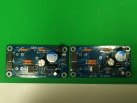
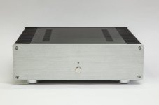
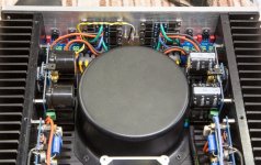
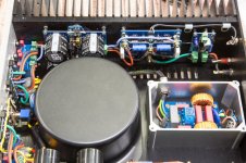
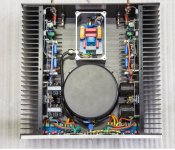
I finally got to complete my Le Monstre 2024 build this afternoon. Some pics are shown here - but basically, there is a line filter with ICL first, then switch, transformer, rectifiers are mounted on the front panel, then the 7815 pre-regulators followed by the main PSU and the amp boards. Lastly, the speaker protection modules.
Now off to listen!!!
Now off to listen!!!
Attachments
I've just soldered the SSPs and was wondering which value to use for Rrs ?
I myself would not use Rrs.
If the protection would trigger, I would want to switch off, disconnect speakers, and measure the amp to locate the fault first.
After all that, it would have discharged by itself.
If not, just short the two solder pads with a 1k leaded resistor.
But if you do want auto reset, then use 1M.
Patrick
Last edited:
I finally got to complete my Le Monstre 2024 build this afternoon. Some pics are shown here ....
Nice pictures. 😊
Patrick
Details of the preamp is also posted, timely concluding in 2024.
www.diyaudio.com/community/threads/preamp-for-hiraga-le-monstr-2024.421562/
Merry Christmas,
Patrick
www.diyaudio.com/community/threads/preamp-for-hiraga-le-monstr-2024.421562/
Merry Christmas,
Patrick
Hi all and many Christmas greetings!
I was flirting with the Le Monstre amplifier for some years now, but, although I have gathered all the necessary components, never got into building one. For the input JFETs, I have plenty of 170s and some J74s, all tested and genuine, but, alas, all BL grade. So, reading this thread, I finally got a solution with the current source bypass "trick". Regarding the current source bypass circuit, Patrick suggests using current production 2SK208-GR JFETs. I wonder if I could use some 2SK117-GR that I have in hand or sacrifice a couple of 2SK170-BLs for the current sources.
Regards,
Evangelos
We actually used resistors in our final build.
The cascode voltage is very constant.
So little advantage in using a current source.
Although it is in theory possible to use BL grade JFETs it is still recommended to use GR grade, and thus not requiring so much bypass.
Happy New Year,
Patrick
The cascode voltage is very constant.
So little advantage in using a current source.
Although it is in theory possible to use BL grade JFETs it is still recommended to use GR grade, and thus not requiring so much bypass.
Happy New Year,
Patrick
Last edited:
Too difficult to find GRs. I will try my BLs.Although it is in theory possible to use BL grade JFETs it is still recommended to use GR grade, and thus not requiring so much bypass.
Happy New Year!
Evangelos
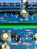
Is the pin out of the transistors the same as in the first post (photo)? Is the pin out of Q3 JILIN SINO ss8550 different to the On Semi version?
Just asking as the orientation of the transistors in the photo don’t line up with the markings on the PCB and data sheets. Did you use different transistors or am I missing something?
Hi @freebee - apologies for the slow response - I somehow missed your first comment in #294 above. There were a few different transistors trialled for Q3/4 before selecting SS8050/8550 so the photos likely are from one of those test builds.
SS8050 and SS8550 have the pin out E-B-C - so when inserting them in the board make sure to respect the silkscreen on the board for Q3/4. You can always trace the tracks on the board as well to check against the schematic over in the group buy thread. Provision was made for paralleling Q3 or Q4, so you can use either position Q3 or Q3a etc as suits.
Great to see the build progressing!!
I have been listening to the build shown above and very much enjoying it.
Hi @woodturner-fran, Thanks for clarifying that.
Taking my time for this build and am still waiting for some parts to arrive.
Regarding Q2, 2J74, what is the actual pin out? The pin out in the data sheet appears different (reversed) than the PCB markings. Maybe it’s the picture on the data sheet that’s confusing me as it shows the flat side at the top.
Any idea what the correct orientation is?
Will show some photos in a couple of days of the progress made 😄.
- Home
- Amplifiers
- Solid State
- Hiraga Le Monstre 2024