No , The Japanese came up with many unique derivatives. Yes, the "basics" (research and papers) were the Americans and British.These were Americans and British. The Japanese were only engaged in manufacturing.
Widlar , Wilson , Hawksford. But... the Japanese actually applied this to the real world.

Dear sir i do some search i found a schematic. This is what that you are talking about?only basic 3 points:
1. maximum linear gain open loop of each stage, especially the input stages.
2. compensation outside the feedback circuits, local frequency feedback is also not suitable
3. the most linear output power cascade - as a rule, this is the Lokanti cascade.
We are not considering the remaining points regarding thermal stability and a stable operating point.
not to go too deep into the topic
Well done, bravo!!!I don't believe a word you say 🤣
"don't look up"))))🤣
NoDear i do some search i found a schematic. This is what that you are talking about?
very funny picture).
Who needs that ? "mine is longer" ? Rather have simple. My target is 20-30ppm with minimal parts and less FB. Super stable into allYou can do this well, but an NFB depth that exceeds 100 dB at a frequency of 20 kHz will not work with these circuits
loads .... runs cool. Easy to repair , good PSRR , etc.
OS
Sir my last question about progressive correction compensation is that they based on op amp designs?We are not considering the remaining points regarding thermal stability and a stable operating point.
not to go too deep into the topic
such a high LG (nfb strength 100dB@20k) can only be achieved with a composite design
such a high LG (nfb strength 100dB@20k) can only be achieved with a composite design
the best comment for the last 2 pages of this topic. Cool.
Look attach, and dont tell Dadod)))such a high LG (nfb strength 100dB@20k) can only be achieved with a composite design
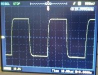
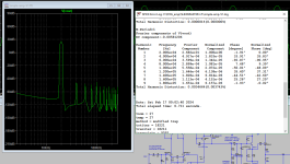
At maximum power, harmonic distortion of the audio signal falling within the audio frequency range does not exceed 0.00085% at a load of 3.8 Ohms, and 0.00065% at a load of 7.5 Ohms.
When the output signal amplitude is half the maximum, the harmonic level drops to 0.00007% at a load from 3.8 to 7.5 ohms.
Intermodes falling within the audio range do not exceed 0.00007%.
P.S. don't trust anyone - "don't look up"😆
Attachments

this is the simplest implementation of progressive compensation, with large values 139 dB was achieved at a frequency of 20 kHz, another question arose related to the technology of components and the implementation of the finished product, and an even more ambitious question: with a negative feedback depth of more than 100 dB, does it make sense to make maximum linearity or does it no longer matter? because the hearing aid no longer hears any difference - i.e. The amplifier topologies are different, but they sound the same....
Who needs that ? "mine is longer" ? Rather have simple. My target is 20-30ppm with minimal parts and less FB. Super stable into all
loads .... runs cool. Easy to repair , good PSRR , etc.
This has already happened, this is the concept of novice radio amateurs, passed in the late 80s of the last century....
That's when this concept end died... Couldn't get good quality sound.
Any class high quality amplifier is the amplifier that was posted,built,tested from dyer's in real world,not just simulated or theoretically analized!
We can't listen music from theory!
Share your schematic,pcb and wait for dyer's to build.
My opinion of course.
thimios.
We can't listen music from theory!
Share your schematic,pcb and wait for dyer's to build.
My opinion of course.
thimios.
High quality any class amplifier is the amplifier that was posted,built,tested from dyer's in real world,not just simulated or theoretically analized!
We can't listen music from theory!
Share your schematic,pcb and wait for dyer's to build.
please read the names of the attached pictures, type them into Google and....talk about music theory
P.S. We haven't talked about music theory in this thread yet 🙂
Operational amplifiers are designed by very good engineers, but some op-amps are not suitable for audiophile use - this means that its main purpose is not sound. Moreover, the best microcircuits for sound are usually military technology (for example, missile aiming correction)Sir my last question about progressive correction compensation is that they based on op amp designs?
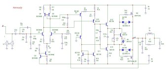
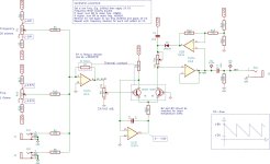
I looked at the diagram you posted in the first post. Here is my vision of a similar topology (see attachment),
peculiarities:
*linear openloop gain 95dB+/-1.5dB
*output power 100 watts into 4 ohm load
*distortion less than 0.002% in the frequency range 1kHz - 20kHz
*not frequency compensation circuits in the feedback circuit, i.e. only progressive compensation.
you can type the diagram yourself in your application and see the characteristics.
Attachments
Interesting sir you explained it in details. Many thanks sir for the knowledge you share with us.Operational amplifiers are designed by very good engineers, but some op-amps are not suitable for audiophile use - this means that its main purpose is not sound. Moreover, the best microcircuits for sound are usually military technology (for example, missile aiming correction)
I looked at the diagram you posted in the first post. Here is my vision of a similar topology (see attachment),
peculiarities:
*linear openloop gain 95dB+/-1.5dB
*output power 100 watts into 4 ohm load
*distortion less than 0.002% in the frequency range 1kHz - 20kHz
*not frequency compensation circuits in the feedback circuit, i.e. only progressive compensation.
you can type the diagram yourself in your application and see the characteristics
Also thanks for posting the schematic.
Newbie post
Is there an example of (lets say classic) Class AB amplifier schematic not requiring anything to be added/modified or removed. But adequately be called close to hifi ?
Thanks and regards.
Is there an example of (lets say classic) Class AB amplifier schematic not requiring anything to be added/modified or removed. But adequately be called close to hifi ?
Thanks and regards.
Music theory considers melody, rhythm, counterpoint, harmony, form, tonal systems, scales, tuning, intervals, consonance, dissonance, durational proportions, ...We haven't talked about music theory in this thread yet
That sounds fun. I suppose it could relate to what HQ in the final stage is ?
It relates more to sources. I create some of my sources "RAW" (below). Quite the opposite as amps - to make an oscillator.
I'm going to buffer the saw and create a voltage controlled pulse at 10V p-p. Really get a perfect 1V/oct with that tempco resistor. More fun.
It's cool measuring the harmonic content of some of these complex waveforms.
OS
Attachments
Yeah , DIY store "Badger" or any similar "LIN" (1972).Is there an example of (lets say classic) Class AB amplifier schematic not requiring anything to be added/modified or removed. But adequately be called close to hifi ?
Thanks and regards.
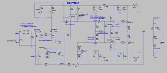
Close to hi-fi ? Actually better than most OEM's if built carefully ....
I'm just using it for a sub , but I have heard so many of these - transparent and simple...
Can't get any more "classic" than that. DIYA store "Badger" is a part or two away from below amp.
Nearly impossible to screw up design that has lower THD (below 3) than a typical OEM 150$ receiver.
It won't be any better than the filter (below 4) with TL084 op-amp that feeds it. I feed a pair of these with my Xonar DX sound card -
EVERY brush/ cymbal - "holographic image". The amp just "disappears" (as it should).
PS - I built this design 17 years ago , when I was a "NOOB" !!
OS
Attachments
I can't see extreme low distortion,0.002% is an easy target.Operational amplifiers are designed by very good engineers, but some op-amps are not suitable for audiophile use - this means that its main purpose is not sound. Moreover, the best microcircuits for sound are usually military technology (for example, missile aiming correction)
I looked at the diagram you posted in the first post. Here is my vision of a similar topology (see attachment),
peculiarities:
*linear openloop gain 95dB+/-1.5dB
*output power 100 watts into 4 ohm load
*distortion less than 0.002% in the frequency range 1kHz - 20kHz
*not frequency compensation circuits in the feedback circuit, i.e. only progressive compensation.
you can type the diagram yourself in your application and see the characteristics.
I have so many amplifiers far lower than this.
On the other hand, I don't believe that the only goal is very low distortion. After all, high fidelity is one thing and musicality is
another. I think that in pursuit of absolute high fidelity we sacrifice musicality.
I would glad to test your suggestion in the future if a pcb is available.
I can't see extreme low distortion
But I don’t see the dependence of distortion on frequency))) for such a simple design
May be.0.002% is an easy target.
I have so many amplifiers far lower than this.
At one point at one frequency such distortion is not a problem.
high gain linearity in the audio frequency band open loop is all of the things you listed combined.On the other hand, I don't believe that the only goal is very low distortion. After all, high fidelity is one thing and musicality is
another.
- Home
- Amplifiers
- Solid State
- High quality class AB 100 watt amp