Did you get a chance to measure the dispersion/directivity of this tweeter on a stick?

Lots of eq to get there. More here.
My polar is not exact either. Just moved the mic and measured with a laser in steps.

I personnally would size the smaller baffle for the mid and tweeter 24cm wide with large radius and the mid placed 18cm from the upper edge:
I am in no hurry to select the woofer. I am currently building a prototype of the trapezoid mid-tweeter baffle.... This will be used to collect polar response data from the M74A, which in turn will be used to select the appropriate tweeter.
The comment @Kwesi makes above is an important one to consider in the overall balance and slope of directivity that the finished speaker will have.
A minimal flat baffle area is almost always a good thing, but having the edge of the cabinet very close to the driver will mean that you get maximum diffraction loss. Whether this is a good or bad thing depends, but it is a thing that needs to be considered.
This is an M74 simuated in a minimal enclosure 180 mm wide and 200 deep with a 38mm roundover ot thereabouts (from memory it is the A profile).
You can somewhat ignore the frequency response other than the fact it shows the gain of the baffle and slight waveguide infront of the driver, but the directivity will be pretty close to real.
You can see that the DI is smooth but rising due to the diffraction loss. This same driver in a baffle sixed for an 8" woofer has a much more constant directivity of 5dB or so over most of it's range. I have seen that in practice from a speaker @jcga made, using a T25B, M74B and 2 x Purifi 8" drivers. I "designed" a very small 5mm deep waveguide for the T25B to match the M74B for him, there was some edge diffraction from the baffle being the size of a 8" woofer and having too much flat area around the tweeter as the cabinet was already built but it was still decent.
The SB tweeters do not match very well in directivity terms to the Bliesma drivers they tend to increase the slopes of the furter off axis curves due to their dimensions. I have a pair of M74P in a cupboard and a pair of T25B next to them.
Kimmo has been posting some graphs and slope amounts now Vituix has been changed to add that function. I think this is useful to consider in light of the above when choosing a tweeter and deciding on the right cabinet to built. It has a strong effect of the type/slope of directivity that you will get.
https://www.audiosciencereview.com/...onstant-linear-directivity.58560/post-2141848
https://www.audiosciencereview.com/...onstant-linear-directivity.58560/post-2149787
Attachments
All of the simulation tools are an interesting concept…..along with the notions suggested by a preferred directivity index’s and whatnot……….a good developmental baseline for someone with the intent of producing a commercial speaker that can perform well in most home environments……..
BUT…..DIY has the greatest advantage for those that prescribe….the ability to create an optimal system for user’s unique acoustic space and sonic preferences. If using a combination of theory, simulations AND voicing the designer is most likely to succeed in their efforts.
Voicing is hard work and requires some listening training, but pays huge dividends to those that practice it. I would assert that a pair of adjustable straight mic stands placed in the listening space along with the OPs mid domes which will play the full telephone band safely with a simple high pass filter would be more revealing and helpful than any software simulation or acoustic measurement ever could. Midrange use and testing offers this unique ability……..exploit it to the fullest. One of the most helpful mix and mastering tools I have at my disposal is a pair of full range driver mix cubes. Run in stereo and mono, I get 95% of my mix from these alone……if it sounds balanced and has the intended spacial separation, it will sound good almost anywhere…….the last 5% is primarily bass performance, high end clarity and fluff. Of course there are limitations…..this is a near field exercise which removes the influence of the room…….but this proof of concept works every time regardless in assuring the recording is providing everything that’s fundamental……..what the end user’s acoustic space does to it is inconsequential since I have no control over it.
Funny, I have missed the ASR thread that fluid linked at post 123. Very intersting and rare material...
I have followed Kimmo's progress as designer at the national forum for a long time and I am very pleased to notice that he now prefers low DI for domestic speakers -and explains why. 10+ years ago his projects were super directive (cardioid and horn or wmtmw towers) because he wanted to fight against his living room acoustics by force. He unfortunately has difficulties in expressing his concepts and opinions in an easy way for dummies... like me.
The most important, fundamental design objective in loudspeaker design should be the target use and acoustics of the environment. For well damped single-seat hifi studio the design has different ideals than for a normal quite reflective living room and casual listening while walking between the seat and the fridge! This same issue must be kept in mind when comparing and evaluating commercial speakers, by measurements and subjective impression. Preferencies are allowed, also for final voicing.
I advice every hobbyist to listen to different kinds of good speakers and rooms - differencies between "good sound" are huge!
The DI curve slope is a interesting topic. Since most systems start with DI=0 (subwoofer) and ends up with DI>=10 (tweeter) , what is the best way to connect the DI end points. An omni and slim towers with low DI can provide a relatively constant slope DI to connect the dots. Horns and cardiods can often cause slope changes, producing a knee in the DI curve. Is a good DI curve defined by relatively constant slope or just no local discontinuties? I aim for a relatively constant slope.
[edit] I have never found an answer to "how fast can the DI slope change, and still be acceptable" ? Maybe its a preference.
[edit] I have never found an answer to "how fast can the DI slope change, and still be acceptable" ? Maybe its a preference.
Thank you for your thoughts. When I read @Kwesi wrote, I assumed it pertained to a rectangular baffle. But I read it a few more times and I think his statement ...A minimal flat baffle area is almost always a good thing, but having the edge of the cabinet very close to the driver will mean that you get maximum diffraction loss. Whether this is a good or bad thing depends, but it is a thing that needs to be considered.
... is more generally applicable. In any case, my trapezoid baffle is 250 mm wide at the base, and 288 mm high, and the midrange is located 186 mm from the top edge. So my configuration is very close to his recommendation.I personnally would size the smaller baffle for the mid and tweeter 24cm wide with large radius and the mid placed 18cm from the upper edge
I appreciate everyone's thoughts about directivity. Once the drivers are selected and the baffle layout is designed, the directivity is mostly fixed at that point. So it is well worth hashing over the details now.
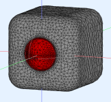
This is the current baseline configuration. The trapezoidal baffle is sized just large enough for the M74A and a small 70 mm frame tweeter, plus a 37 mm edge radius on all four edges.
My current plan is that the trapezoid baffle will be positioned in front of the woofer cabinets (closer to the listener) by at least 37 mm. This will provide the most reflection-free environment for the mid and tweeter. Unfortunately, it complicates the diffraction simulation a bit. The transition from the trapezoid to the upper woofer baffle is a more complicated geometry that is beyond the simple diffraction model in VituixCad. The question is should the trapezoid be modelled in isolation? Or should it be modelled as part of the full cabinet baffle including the woofer baffles?
For the tweeter, there is no significant difference in simulating it either way. But for the M74 mid, there is a difference.
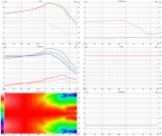
Here is the simulated M74A diffraction response for the case of the isolated trapezoid
And now here is the simulated M74A diffraction response for the full cabinet baffle
In the next post I will show how these two diffraction assumptions impact the overall system level simulation
Here is the system level response assuming the midrange trapezoidal baffle is isolated.

And finally, here is the system level response assuming the midrange trapezoidal baffle is joined to the woofer cabinet baffles

The crossover filters are slightly different for the two cases. In terms of directivity and sound power, there is not a big difference, in fact it is rather subtle. But that does not mean it is not an important difference.
I wanted to post all of this detail so that we are all on the page and we can have a good discussion about this.
j.
And finally, here is the system level response assuming the midrange trapezoidal baffle is joined to the woofer cabinet baffles
The crossover filters are slightly different for the two cases. In terms of directivity and sound power, there is not a big difference, in fact it is rather subtle. But that does not mean it is not an important difference.
I wanted to post all of this detail so that we are all on the page and we can have a good discussion about this.
j.
I agree. A speaker intended for a wide variety of listening rooms and environments should be designed with a primary emphasis on the CTA-2034 performance curves.All of the simulation tools are an interesting concept…..along with the notions suggested by a preferred directivity index’s and whatnot……….a good developmental baseline for someone with the intent of producing a commercial speaker that can perform well in most home environments…
Yes, I agree here also. Unlike some of my earlier projects, this project is not intended to be replicated by other builders, or built for other people in their rooms... this is my speaker system for my room. I feel that high quality measurements and accurate simulation / modelling can get me 95% of the way to excellence. That last 5% requires critical listening and subjective voicing.DIY has the greatest advantage for those that prescribe….the ability to create an optimal system for user’s unique acoustic space and sonic preferences. If using a combination of theory, simulations AND voicing the designer is most likely to succeed in their efforts.
@Juhazi - well said !
Since most systems start with DI=0 (subwoofer) and ends up with DI>=10 (tweeter) , what is the best way to connect the DI end points. An omni and slim towers with low DI can provide a relatively constant slope DI to connect the dots. Horns and cardiods can often cause slope changes, producing a knee in the DI curve. Is a good DI curve defined by relatively constant slope or just no local discontinuties? I aim for a relatively constant slope.
[edit] I have never found an answer to "how fast can the DI slope change, and still be acceptable" ? Maybe its a preference.
I think preference has something to do with it, and also the room and the distance from listener to speaker. For me, in my listening space, I seem to be rather tolerant of variations in DI. I have a pair of speakers with a very linear slope to the DI curve, and I have others which rise smoothly from 0 dB to 5 dB at 1k, then remain constant at 5 dB up to about 6k, then rise smoothly above that. I cannot say that I have a preference.
j.
Theory vs practical
1. The dispersion is going to change when you model just the MT, vs the full cabinet with the twin woofers. That part is clear.
When you go to measure, will you measuring the separately, or together? The horizontal you can measure the cabinets together with a little extra work. The vertical, it will be LOT of extra work. You'd have to solve that, perhaps bolt on the trapezoidal cabinet. But at that point, you might wonder- why didn't I just build it as one piece?
For the speaker in post 52 I made the decision to model the full cabinet before any wood was cut. But the practical decision to measure separately,
So the sim is not perfect representation of reality. But I'm OK with that. Because I know that the CTA2034A/anechoic measurement by a NFS is also not a representation of reality of the speaker in my room.
2. What reason are there for choosing woofer bin width of 35cm?
3. Do you plan on moving the MT cabinet forward of the woofer bin 37mm?
Last edited:
I plan to build a two-part cabinet sometime in 2025 and have thought about the nightmare of the vertical spinorama measurements. My cabinets will have curved sides which will make laying it on its side even a more pain-in-the-a$*. And they will be HEAVY.
My solution (at least what is in my head right now) is to cut out an MDF sheet in the shape of the baffle - one for the bass bin and one for the Tweeter-midrange cabinet. When measuring the T-M cabinet I can put the fake/temporary bass-bin baffle on the turntable in the correct orientation. And repeat for the real bass bin (which will still be heavy and awkward by itself) with the fake/temporary T-M baffle positioned accurately where the actual T-M cabinet would sit.
My solution (at least what is in my head right now) is to cut out an MDF sheet in the shape of the baffle - one for the bass bin and one for the Tweeter-midrange cabinet. When measuring the T-M cabinet I can put the fake/temporary bass-bin baffle on the turntable in the correct orientation. And repeat for the real bass bin (which will still be heavy and awkward by itself) with the fake/temporary T-M baffle positioned accurately where the actual T-M cabinet would sit.
The larger area of the woofer baffle below will have an impact as the simulation suggests and will offset the tendency of the DI to rise from that larger vertical surface.My current plan is that the trapezoid baffle will be positioned in front of the woofer cabinets (closer to the listener) by at least 37 mm. This will provide the most reflection-free environment for the mid and tweeter. Unfortunately, it complicates the diffraction simulation a bit. The transition from the trapezoid to the upper woofer baffle is a more complicated geometry that is beyond the simple diffraction model in VituixCad. The question is should the trapezoid be modelled in isolation? Or should it be modelled as part of the full cabinet baffle including the woofer baffles?
I would suggest that avoiding joins and knuckles wherever possible and having the separate baffles flow into each other as much as possible will produce a measurably smoother result, and will also look nicer. You can see in the full baffle sim the smaller edges on the woofer top introduce some ripple. It is a small amount and not a major concern but it can be avoided if you want to.
I would not round the bottom edge of the mid cab or place it forward, I would make the top trapezoid a bit bigger if you go with 10" woofers. It won't add any real negative diffraction effect but it will allow the top and upper woofer cab to join together better than they do in your drawings.
One other thing to remember with the tweeter sim is that most 1" domes will not be quite so directional.
It means you cannot offset the mid cabinet(in the deep direction plan) for time delaying it in the filter overlapp with the woofer if you want to figth difraction if i understand you. Fortunatly, Jim can use delay with the Hypex DSP.
Maybe for the passive filter guy a tilted mid cabinet baffle à la Wilson Audio Watt/Puppy is the way to do.
Whatever it is a personal loudspeaker thread devlopment, I hope Jim will share his good cabinetry wood skills about that MT how to like he is often do !.
I am looking forward to read the thread whent it comes to the patern of the tweeter vis-à-vis of the cabinet shape and mid dome about that Directivity Index.
🙂
Regarding vertical polar measurements: In general, vertical polar scans are not needed, they can be very difficult to perform correctly, and add little value. There are some key caveats: (1) This applies to multi-driver speaker system where the drivers are vertically aligned, (2) the drivers themselves have isotropic radiation patterns, meaning they are conventional cones or domes, and any waveguides have the same vertical and horizontal pattern (for example round waveguides. Ribbon tweeters, AMTs, bi-radial horns, elliptical waveguides, this rule does not apply to those.
Given the above caveats, the vertical polar response of a speaker system is dominated, almost completely dominated, by the interactions of the drivers, the spacing, and their magnitude and phase responses. The effects of baffle shape are secondary at best. You can prove this to yourself by modeling some examples in VituixCad. Or you can do it the hard way, like I did twice.
Well that decision is still quite a ways downstream...
Given the above caveats, the vertical polar response of a speaker system is dominated, almost completely dominated, by the interactions of the drivers, the spacing, and their magnitude and phase responses. The effects of baffle shape are secondary at best. You can prove this to yourself by modeling some examples in VituixCad. Or you can do it the hard way, like I did twice.
Thanks for that thought. It has been on my mind as well. There are construction and aesthetic advantages to doing it the way I have planned, and a fully radiused trapezoid may allow future woofer upgrades to happen more seamlessly. But there are also some compelling reasons to do it the way you outlined... as you correctly pointed out.I would suggest that avoiding joins and knuckles wherever possible and having the separate baffles flow into each other as much as possible will produce a measurably smoother result
Well that decision is still quite a ways downstream...
Yes, nor are 3" dome midranges. If simulate the M74A as a 74 mm disc, the directivity is significantly narrower than the data from @HiFiCompass or from the Bliesma spec sheet. The closest I can get to matching the published data is to simulate it as a 67 mm disc. My 67 mm sim has an Sd of 35 cm^2 vs 50 cm^2 Sd for the actual driver. This is why I need to make a prototype baffle and take some data with a real driver.One other thing to remember with the tweeter sim is that most 1" domes will not be quite so directional.
Compare to the normalized polar I posted above. That is pretty much worst case diffraction loss, the Hificompass and manufacturer data are both 2pi and not comparable to 4pi in a regular cabinet. Real data is always better but you should be well enough in the ball park if you can find something to more closely match the BEM sim.Yes, nor are 3" dome midranges. If simulate the M74A as a 74 mm disc, the directivity is significantly narrower than the data from @HiFiCompass or from the Bliesma spec sheet.
A test proto I made ten years ago, mid 4" Audax cone, tweeter Fountek ribbon in shallow carved wg. Final woofers were supposed to be 10" and box like Avalon Time. I took many measurements with different edge shapes. But then I realized how big they are and that I don't need them... And some years after that I found a faulty pair of stone-cabinet WWMTM that I modified to dsp-active WWMT, they serve as bedroom speakers now


There’s one factor that in the real world will override all of these considerations on the performance factor…..and that’s the forward midrange performance that a dome mid will create……it’s not a smoothness, distortion or other quantifying factor….it’s time based and the overwhelming majority of the fundamentals within a complex piece of music will arrive first from the apex of the dome…..unaffected by diffraction who’s effects will be swamped by the remaining system components and the acoustic space.The larger area of the woofer baffle below will have an impact as the simulation suggests and will offset the tendency of the DI to rise from that larger vertical surface.
I would suggest that avoiding joins and knuckles wherever possible and having the separate baffles flow into each other as much as possible will produce a measurably smoother result, and will also look nicer. You can see in the full baffle sim the smaller edges on the woofer top introduce some ripple. It is a small amount and not a major concern but it can be avoided if you want to.
I would not round the bottom edge of the mid cab or place it forward, I would make the top trapezoid a bit bigger if you go with 10" woofers. It won't add any real negative diffraction effect but it will allow the top and upper woofer cab to join together better than they do in your drawings.
One other thing to remember with the tweeter sim is that most 1" domes will not be quite so directional.
As engineers, we’ve come to appreciate these drivers like fluorescent highlighting markers…….and that’s exactly how they are perceived when listening………..a whole page of information summed up in a few words…….this is something that needs to be experienced in the mid to far field beforehand…………forget about diffraction…..it’s an insignificant factor here. Time and space………that’s all that matters. A listener will find that dome mids are not one bit tolerant of non symmetrical acoustic spaces either nor do they have a wide sweet spot that DI theory suggests……they’re like sonar, …….and the playback acoustic space overrides that baked into the recording.
I can’t see any value in simulating an MT baffle at this point unless the above has been accounted for…….and that’s VERY likely going to come down to the need for the dome mid to be in a waveguide to offset the driver…….which creates a whole new set of challenges with integration to a tweeter.
Last edited:
mayhem13, with multichannel dsp it is easy to set some delay for the (dome) mid, if necessary. Acoustic center in z dimension is impossible to simulate, only measurements can tell that. And same applies to cones and ribbons as well. Xo around 3-4kHz is very sensitive to timing yes, but a symmetrical LR2 with correct timing will sound so sweet! Vertical off-axis is always a challenge and the design axis must be very close to listening axis of the end user.
Yes, in all of my active designs I manage the timing of the drivers. I apply digital delay to all of the drivers to align them with the driver furthest from the listener (usually the woofer). Rough timing is based on distance measurement (tape measure), and final adjustment is based on examining the impulse response. Sometimes this delay is further adjusted during the subjective voicing process.
Both yours and hifijim´s creations look very alike Albert Von Schweikerts VR-4 speakerdesigns from1995-96.A test proto I made ten years ago
I had a original pair from 1998 that Albert upgraded in 2001.
This $3 K pair of speaker has been my referencespeaker sinse 2001, so sold my $25.000 usd pair Revel Ultima Salons first gen.
So this consept have huge possebilitys to play real hi end sound!
regards John
- Home
- Loudspeakers
- Multi-Way
- High Performance 3-way based on Bliesma M74A