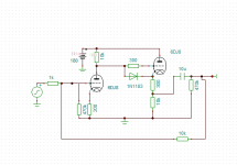
OK, that makes it easier. You can do a common cathode stage, with a cathode follower, then feedback to the grid of the common cathode stage. Set the ratio of feedback resistor to the grid resistor (that's a series grid resistor, not the grid leak!) to 5:1. A good choice of values so as not to excessively load down the sources and, at the same time, to not have instability from stray capacitances, would be 20k and 100k. You might have to put a small cap (10-30pF) across the 100k resistor to avoid ringing. And, of course, use 1k grid stoppers to prevent oscillation.
Well I thought that common cathode stage + cathode follower needs 3 triodes. (Newbie in tubes)
Anyway, thanks a lot SY.
Anyway, thanks a lot SY.
It will need three stages if you want it to be noninverting (trivial to account for downstream). But your schematic is conceptually correct.
It does not need to be non-inverting. Just to recheck values, to do some simulations and to build it 🙂.
As you drew it, you have a 1k input impedance, which is asking a bit from your sources. 😀 I'd also look at boosting the open loop gain and increasing power supply rejection by bypassing the first stage cathode resistor (or using diode or battery bias). A CCS load for the first stage will take that even further. You absolutely want gridstoppers on both stages.
But you have a good base for experimenting.
But you have a good base for experimenting.
SY, I downloaded CCDA manual, so I'll read it all now. Also, if I dont need so much gain, I dont have to use bypass capacitor too, right?
With the feedback loop, the cathode bypass won't change your open loop gain very much, but it will increase power supply rejection and most likely reduce distortion.
Well I thought that common cathode stage + cathode follower needs 3 triodes. (Newbie in tubes)
Anyway, thanks a lot SY.
If you want to achieve lower impedance on the output you will need 3 triodes, the first one like a gain stage and the second and third ones in parallel like a catode follower.
A single ECC88 CF will give you under 200R output impedance- why would it need to be lower?
ECC 88 if used in a right way can be very good for a gain stage, for the catode follower u should use different tube.
E182CC can be a good double triode for the catode follower. More current on the output and more dynamic sound.
Why? gm for ECC88 is 10 mA/V, so source impedance is low (100R). In CF mode, distortion is insanely low.
Other tubes can work, but why bother if you're already mounting some ECC88 on the chassis?
edit: Just looked at E182CC datasheet. Slightly higher gm (15mA/V) but needs a whopping 36mA per section to achieve this. If 100R source impedance is too high, then it can get you 67R if that will make a difference, though at a major cost in power supply and heat. Can't comment about linearity.
The datasheet says 15mA/V, only marginally higher than ECC88. And as I said before, it requires more than three times the current to get a largely unnecessary (for preamp use) increase in gm.
You're confusing plate current with transconductance.
You are right, i was talking abt catode current, anyway, from my experiance (personal opinion) the tubes like E182CC, 12BH7... are better solution for catode follower then ECC88. I'ts worth to try.
- Status
- Not open for further replies.
- Home
- Amplifiers
- Tubes / Valves
- High-End preamplifier with ECC82!