OK Terry, where's the pics?
I'll have to figure out where I left my Etch-A-Sketch... 😀
As some people may have already figured out, I'm certainly not a Photographer by any means. However, I'll see what I can do about getting some pics posted.
Best Regards,
Terry
OK Terry, where's the pics?
Hi Pano,
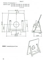
I have a picture of the Radian Coax driver mounted on a 2X2 foot temporary open baffle. The picture was taken in DaveR's listening room. You'll also be able to see the 200% Norweggian's DIY Tube amp and headphone rack in the background!
😀
Best Regards,
TerryO
Last edited:
Hi Pano,
I have a picture of the Radian Coax driver mounted on a 2X2 foot temporary open baffle. The picture was taken in DaveR's listening room. You'll also be able to see the 200% Norwegian's DIY Tube amp and headphone rack in the background!
😀
Best Regards,
TerryO
Attachments
FWIW, offsetting the driver in both planes at some acoustic ratio is a good plan.
GM
Hi Greg,
The panals are sized at 2 X 2 feet just as a matter of convieniance and Dave and I agreed to the vertical 4 inch offset (the driver center is 8 inches from the top and 16 inches from the bottom). This was/is a test baffle and I'm certainly open to suggestions. Cardboard extensions and cutting the baffle narrower are possible and we can certainly rotate the baffles .
So far the only consideration has been developing a crossover which would work with the Radian. I believe Dave arrived at 2100 Hz as the frequency that worked best in a Series Crossover.
Which Acoustic Ratio (and/or baffle size and shape) would you suggest?
At this point all that's been done is putting together a couple of series crossovers for use.
Best Regards,
Terry
Greets!
Well, you don't want an offset that has a common denominator such as in this case [4"]. 😉
The most common used in room layouts are the golden ratio or odd order fractions [3rds, 5ths, etc.]. If you want the driver more centrally located, then an acoustic ratio is best:
1.26:1.41
1.14:1.39
1.25:1.60
1.28:1.54
There's many more, but all these should give you plenty of options.
Baffle size is usually either a BIB thing or to keep it reasonably small, only make it large enough to support the driver down to its HF mass corner [2*Fs/effective Qts] and if more bottom end is required, add a 'sub' system.
Ideally the baffle would be a free form shape to average out its eigenmodes, but few have bothered since they tend to look really weird in most lifestyle decors short of a retro Salvador Dali mind bender.
Anyway, just wanted to give you something to consider for the final baffle design.
GM
Hi Greg,
Which Acoustic Ratio (and/or baffle size and shape) would you suggest?
At this point all that's been done is putting together a couple of series crossovers for use.
Best Regards,
Terry
Best plan might be to download Tolvan's The Edge software and run some simulations. The best baffle may depend a bit on your chosen crossover point.
Bill
Which Acoustic Ratio (and/or baffle size and shape) would you suggest?
At this point all that's been done is putting together a couple of series crossovers for use.
Best Regards,
Terry
Well, notwithstanding that the crossovers should be done after the baffle shape is decided, an asymmetrical trapezoid is the best (simple, floor-mounted) shape I've found for diffraction.
Best plan might be to download Tolvan's The Edge software and run some simulations. The best baffle may depend a bit on your chosen crossover point.
For the 'sub', if they use one; the HF XO's WLs will be < ~6" in diameter, so will 'fit' inside the woofer.
GM
.......an asymmetrical trapezoid is the best (simple, floor-mounted) shape I've found for diffraction.
This is my baffle shape of choice also as long as the slope is >12 deg, but forum folks for the most part have yet to embrace them.
GM
I'd like to thank Louseymusican, Badman, GM and IG
for all their help, hints and suggestions lately. I'm not sure that there's another Audio Forum anywhere that can supply such consistantly excellent advice on an individual's audio project.
Thank you very much!
Best Regards,
Terry
for all their help, hints and suggestions lately. I'm not sure that there's another Audio Forum anywhere that can supply such consistantly excellent advice on an individual's audio project.
Thank you very much!
Best Regards,
Terry
Last edited:
Don't forget my advice to post photos. 😛
You were going to be the "Surprise Grand Prize Winner", but you went and ruined everything.
Hopefully, I will be able to return the Rolls-Royce and get my money back.
Tearful Terry....

- Status
- Not open for further replies.
- Home
- Loudspeakers
- Multi-Way
- High Efficiency. Definition and Resolution...on a Bargain Basement Budget

