There is no drive there.
Follow the drive back from the drive header pin of the driver board and check all components in series with that pin of the header.
Follow the drive back from the drive header pin of the driver board and check all components in series with that pin of the header.
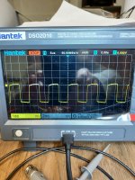
What is the photo in reply #101 showing? I was using the differential probe with the positive probe on the gate and the negative probe on the drain of a low side fet.
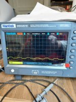
When using the differential probe as before, the positive probe on the gate and the negative probe on the source, I do not get a signal and I just noticed that it also causes the amp to go into protect.
Try using your scope using both channels in differential mode. Don't use the differential probe.
There is a way to make it display one single trace. I don't know what it is for your scope.
Set the vertical amplifier so that the waveform fills about 3/4 of the top half of the display.
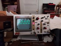
This will likely be easier and give a better image with your old analog scope.
Set the vertical amplifier so that the waveform fills about 3/4 of the top half of the display.
This will likely be easier and give a better image with your old analog scope.

Was the trace aligned to the center reference before probing the FET?
Increase the sensitivity of the vertical amplifier to increase the height of the waveform and then adjust the trigger level.
Is the trigger set to the channel connected to the gate of the FET?
Increase the sensitivity of the vertical amplifier to increase the height of the waveform and then adjust the trigger level.
Is the trigger set to the channel connected to the gate of the FET?
Are the two 'cal' knobs fully clockwise?
I don't see any serious problems but I'd expect the falling side to be more vertical.
Did you try the HF reject position in the trigger section?
The lack of a clear signal could be due to the noise on the output. Removing the outputs and loading the FET location with a small capacitor (0.001-0.01uF) may make it easier to see the signal clearly.
If the 'cal' knobs are the red ones in the center of the channel controls, they are not fully clockwise. I have them in the center of their rotation. Fully clockwise they "click" to a position.
I did not try HF rejection.
I haven't used this scope very much. I am still new to using any kind of scope.
I noticed that the display was jittery.
I will try the settings that you recommended.
Is the 'source' selector lever in the correct position on "INT"?
I did not try HF rejection.
I haven't used this scope very much. I am still new to using any kind of scope.
I noticed that the display was jittery.
I will try the settings that you recommended.
Is the 'source' selector lever in the correct position on "INT"?
This oscilloscope only has INT, CH B, LINE and EXT.
Channel B is the only channel that can be inverted.
Channel B is the only channel that can be inverted.
- Home
- General Interest
- Car Audio
- Hifonics Brutus BRZ1200.1D