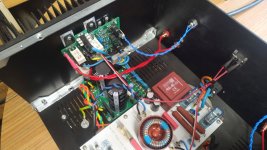
C3 is not a "reservoir" capacitor, it is upstream of the rectifiers. C3 is part of a transformer secondary snubber network.
Amplifier hums. After the inputs are disconnected, there is silence .Everything is connected according to the diagram.
Attachments


I think Bonsai will give you the best info, but here are some thoughts from me:
I'm thinking ground loop. I guess you have no hum with only one input connected, but when both inputs are connected to the source, the hum is there? You can also verify this by using one RCA lead between the inputs.
I would normally place the input connectors close with one transformer (common ground), but it's bit late to change now. I would try to connect the signal grounds between the input connectors, but not to chassis. and run the leads next to each other to one channel, and then continue with the other channels input wire all the way around to the other PCB.
You also could try with loose input connectors and long wires and move them around and listen what happens with the hum.
Another thought: The rectifiers & caps are very close to the amp boards.
The chassis looks nice with the print and all!
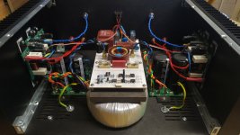
The white PCB is speaker protection?
I'm thinking ground loop. I guess you have no hum with only one input connected, but when both inputs are connected to the source, the hum is there? You can also verify this by using one RCA lead between the inputs.
I would normally place the input connectors close with one transformer (common ground), but it's bit late to change now. I would try to connect the signal grounds between the input connectors, but not to chassis. and run the leads next to each other to one channel, and then continue with the other channels input wire all the way around to the other PCB.
You also could try with loose input connectors and long wires and move them around and listen what happens with the hum.
Another thought: The rectifiers & caps are very close to the amp boards.
The chassis looks nice with the print and all!
The white PCB is speaker protection?
Last edited:
"The white PCB is speaker protection?"
No, it is a soft-start module. Additional features are push-button on/off and mains filter.
ON/OFF Modul with SoftStart, Remote and LC filter V5.0 by MADUDA
No, it is a soft-start module. Additional features are push-button on/off and mains filter.
ON/OFF Modul with SoftStart, Remote and LC filter V5.0 by MADUDA
Platon, sounds like you have a cross channel ground loop - it’s silent with no inputs plugged in, and noisy with inputs. Please carefully read the ‘Ground Loops’ presentation in the link below, and also in the same link ‘Ilimzn’s Excellent Posts on Ground Loops’. For testing this type of problem, just run a standard RCA cable from the one input across to the other so they are joined - this creates the cross channel loop needed to investigate and minimize the noise.
For you specific case:
1. You have two earth points on your chassis. That can cause an earth loop. The rule is ‘Strictly one earth connection to the chassis only!’
2. Probably too late as Rallyfinnen says because you already drilled the holes, but your input connectors should be next to each other with the signal grounds bonded together. In your implementation, you have a huge cross channel ground loop area now between the two inputs
3. As Rallyfinnen notes, keep input connections well away from the PSU. Try lengthening them an running them along the top edge of the chassis and then down to the input connections. You could also try touting the one channel input wire across to the other input then all 4 wires together, drop of at the first amp module and then run the other input around the top edge of the chassis all the way around (via the front side of the amp) to the second amp module. This will dramatically reduce the cross channel ground loop area
4. Did you use a transformer with a GOSS aka ‘belly band’ to reduce the resisted mag field?
5. Remember to rotate your transformer to find the null noise point. This can make a huge difference. Normally the noise null point is within +-60 degrees of the original position, but may be more in some cases
6. Unfortunately, the small brown transformer (RS Components I believe?) you have used in your soft start board has very severe radiated fields so you must keep all input signal wiring well away.
Please try these things, then come back to see if we can improve it.
Last edited:
"The white PCB is speaker protection?"
No, it is a soft-start module. Additional features are push-button on/off and mains filter.
ON/OFF Modul with SoftStart, Remote and LC filter V5.0 by MADUDA
OK!
Could it be that the precharge resistance is a bit high (50ohm + PTC) in case of an amp like this with high bias? Of course it depends on how quickly the bias ramps up after power on, but just a general thought.
I used 6,8ohm precharge resistor on my KX (one for both mono channels), just to cut the first current spike a little and minimize the risk of blowing fuses. I use a 2,5AT main fuse, and that seems to hold up.
Is it connected to a grounded source? Maybe it's a ground loop through the safety ground?
Do you have a ground lifter circuit?
You can test the local ground loop by connecting the two inputs with an RCA cable.
But if you disconnect the input it's silent you said?
Do you have a ground lifter circuit?
You can test the local ground loop by connecting the two inputs with an RCA cable.
But if you disconnect the input it's silent you said?
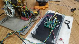
Platon, what is that plate on top of the transformers that the in-rush circuit is mounted on? Is it conductive?
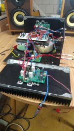
I see it looks like you are using an external power supply in your latest test set-up and still getting a cross channel ground loop. Can you also double check that neither of your speaker output connectors signal return or your input sockets is connecting to the chassis. Use you meter to make sure there is only one connection to the chassis. If you lift the4 safety ground and then measure you should have an open circuit to the chassis.
(I can see you still have tow connections to the4 chassis - you cannot do this - you will get hum.)
Last edited:
Ah, I see now that you have two main transformers! Is it dual mono?
If so, I would try to disconnect everything from any common ground (signal, power, safety-ground) as a test. Just leave the safety ground connected to the chassis.
As Bonsai says, if you have the inputs disconnected, and measure resistance between L&R input grounds or speaker- terminals there should be no connection.
You can also try to shift the polarity on the primary on one of the transformers.
Last edited:
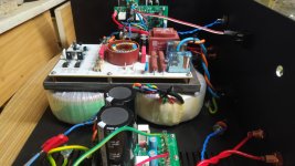
Platon, what is that plate on top of the transformers that the in-rush circuit is mounted on? Is it conductive?
I see it looks like you are using an external power supply in your latest test set-up and still getting a cross channel ground loop. Can you also double check that neither of your speaker output connectors signal return or your input sockets is connecting to the chassis. Use you meter to make sure there is only one connection to the chassis. If you lift the4 safety ground and then measure you should have an open circuit to the chassis.
(I can see you still have tow connections to the4 chassis - you cannot do this - you will get hum.)
I tried without it without it. Thanks Bonsai and RallyFinnen that you are interested
Let’s try to solve this step by step.
1. Please remove ALL connections to the chassis incl any ground lifter
2. Them measure from the 0V on the PSU to the chassis - must be open circuit
3. Check that your HBR resistors are not blown - must measure 33 Ohms each (R9 on the PCB)
1. Please remove ALL connections to the chassis incl any ground lifter
2. Them measure from the 0V on the PSU to the chassis - must be open circuit
3. Check that your HBR resistors are not blown - must measure 33 Ohms each (R9 on the PCB)
Hi
I did everything .Still hum. I disconnected all grounds . The connectors are not connected to the chassis . I don't know anymore. HBR resistors is ok..
I did everything .Still hum. I disconnected all grounds . The connectors are not connected to the chassis . I don't know anymore. HBR resistors is ok..
ok - so now the amp is powered off the external power supply (big transformer on the RHS of your earlier picture) and the soft start is not connected - can you conform that?
- Home
- Amplifiers
- Solid State
- Hifisonix kx-Amplifier