Did you measure resistance between signal GND and protective ground (PE)?
What is the source you connect to? Does it have a grounded plug?
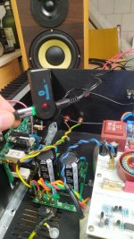
As an example, if it is a laptop sound card, you could disconnect the charger from the laptop, so it's 'floating', to see what happens.
What is the amplitude of the hum (if you have a scope to check this)?
What is the source you connect to? Does it have a grounded plug?
As an example, if it is a laptop sound card, you could disconnect the charger from the laptop, so it's 'floating', to see what happens.
What is the amplitude of the hum (if you have a scope to check this)?
Attachments
Component count is minimized when you place one snubbing resistor across each transformer secondary winding (rather than each diode). With proper choice of resistor value, this reduces the "Q" of the RLC resonant circuit below 0.5 so that no oscillatory ringing is possible. Or as they said in my EE classes at uni, this increases the damping "zeta" of the resonant circuit above critical-damping (zeta=1.0), so that no oscillatory ringing is possible.
The resistor does all the work of "killing the Q". The only purpose of the series capacitor is to decrease the amount of power dissipated in the resistor. Since, after all, the resistor is DIRECTLY ACROSS the secondary winding. You want the impedance of the capacitor to be very very low at the ringing frequency (> 100 kHz) so it doesn't interfere with damping. You also want the impedance of the capacitor to be very very high at the mains frequency (55 Hertz) so that very little current flows in the series RC circuit and heats up the resistor. A good compromise choice for the series C is 0.15 microfarads (150 nanofarads). At 55 Hertz its impedance is 19Kohms and at 100 kHz its impedance is 11 ohms.
_
Thanks Mark,
Sorry it's late getting back to you. I have been 're-wiring' the PSU in an attempt to get the lowest possible noise or other form of interference before looking at the 'cures' side of things.
I had already followed the topic of snubbers and 'Quasimodo" previously but easier (for me) for just one amplifier (or transformer) or 2 it's probably worth just using 'trial and error' together with my scope.
Thanks for your input, I'll let the forum know how I'm getting on.
"I guess it's better to apply the snubbers directly to the RE bridge rectifiers themselves rather than at the transformer side? Reminder that the transformer secondary wires are split at the fuse boxes which separately feed the 2 Ripple eaters around 20cm or so away. I cut put the snubbers at the fuse boxes instead (in which case I'd just use one pair)."
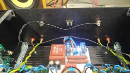
Its important that you apply the snubbers right across the diode bridge with short leads. Its all about keeping the loop area as small as possible - short leads and twisted. You want to do this because if you put it at the transformer side with long wires, the wires will be radiating that hash inside the housing. If you are worried about neatness, you can tuck the snubber under the RE board. What you are doing with the snubbers is softening the diode conduction cut-off by absorbing the charge stored in the diode as it goes into reverse bias. Its the diode reverse bias capacitance forming a tank circuit with the transformer leakage inductance that causes the ringing.
You may hear this as interference if you have an AM radio, or in a really bad case, as a buzz (100 Hz 'tick-tick-tick' sound) on your speakers.
(I will add a snubber on the PCB if I do an update to the RE)
Hi Bonsai,
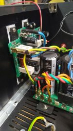
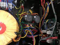
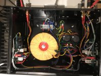
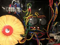
Thanks for the tips. I have just re-wired the Transformer to RE wiring using that large central copped ground between the 'secondary' caps as a star point.
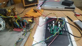
The 2 amps are now connected (fairly crudely at present)
The 'cap bank' is not currently connected and the noise results are far better now with the news wiring 'harness' (< 500 uV with or without dummy load).
The 'damped oscillation' previously reported is somewhat the same but the shape is now irregular rather than 'classic'.
I've added a ground lift right at the transformer 0V output. Two 'back to back' diodes, 100 nF cap and 10 ohm resistor - all in parallel. This reduces the noise by 1/2 to 1/3 of the circuit without it. The RE earths are now left unconnected (was worried about ground loops if both RE grounds were connected at the same time)
Next step is to play around with snubbers at the transformer secondary and try and eliminate that 'quasi' (now) damped oscillation.
Anyway, currently looking better than it was 🙂
Will let you know how I get on.
How are you guys doing with your amp builds?
I have spent a lot of time listening to my KX, and I'm really pleased! Sound is detailed and the amp is 'in control', but not harsh or tiring to listen to even after many hours.
It's a keeper, and I don't regret building it even if I struggled with it sometimes! Thank's again Andrew for the design and support!
My speakers are an easy load, DIY 3ways with a impedance minimum at 6ohms and phase stays within +/-30deg. Efficiency is around 87dB@1W. I don't listen very loud either, but I found I often crank it up a bit higher now, the beloved JLH was a bit short on power..
I run it at high bias all the time, not sure if it actually sounds better, but I prefer it like that. It does get to abt 50deg C after many hours of operation, even with my big heat sinks, but I guess it has something to do with the slight over-voltage too (output rails are ~30V).
I recently went from a Win based laptop as player to Daphile on another laptop, and that has also made a slight improvement in sound. Not sure if the improvement in the digital domain, or just because it shortened my (USB-)cable since the PC is next to the amp now. Also the laptop I use now is isolated from ground, so less risk of ground loops etc.
EDIT: The DAC I'm using is this one: SMSL Sanskrit 10th MK II DAC Review | Audio Science Review (ASR) Forum
I got a new measurement sound card (toasted input on the old one), so I'm still planning to do some measurements on the amp, but at the moment I just enjoy the music 🙂
Last edited:
That’s cool Andreas! Glad you are enjoying the sound.
Just waiting now for Platon to resolve his hum issue!
🙂
Just waiting now for Platon to resolve his hum issue!
🙂
Bonsai, can you send a photo of your amplifier from the inside ??? And draw lines how you wired the ground and signals
Thank you very much
Thank you very much
If you connect just ONE channel from your CD player what happens? Is it still quiet?
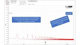
I will make a drawing and post it up. The mains noise floor on my amp Ref 26 W output is -105 dB in class A and -108 dB in class AB (just measured today).
I will make a drawing and post it up. The mains noise floor on my amp Ref 26 W output is -105 dB in class A and -108 dB in class AB (just measured today).
I used a QA 401 distortion analyzer. The signal generator output was set so the kx-Amp delivered 26 W RMS into 8 Ohms (my supply railes are +-28V). The first 15 W RMS are in class A. Then I turned the sig gen off and this is the noise floor ref 26 W output.
Attachments

Hi Bonsai. no,always hum.When I turn off the CD player from the mains then there is silence, or disconnect the RCA .
I used a QA 401 distortion analyzer. The signal generator output was set so the kx-Amp delivered 26 W RMS into 8 Ohms (my supply railes are +-28V). The first 15 W RMS are in class A. Then I turned the sig gen off and this is the noise floor ref 26 W output.
Thanks but i can't see the main frequency...
Do you mean that you took two measurements, one with input signal and the other without?
Plots are without any main signal.
Sorry but it isn't clear for me, what i missing?
To find the noise reference level I drive the amp to full power into 8 ohms with a 1 kHz signal so that the peak output is at 0dB. Then I turn off the stimulus signal and the noise floor ref full output power can be read straight off the graph. There is no change (<0.5 dB) to the noise floor between full output power and no output.
Hi Bonsai. no,always hum.When I turn off the CD player from the mains then there is silence, or disconnect the RCA .
If you are getting hum with just one channel from the CD player but no hum with nothing plugged in, then it sounds like an earth loop. I think I may have misunderstood your original problem statement. The usual rule for this is:-
1. Nothing plugged in and amp quiet - little or no common impedance coupling problem in tne PSU
2. One source lead plugged in. If amp is still quiet then there is no earth loop problem between source and amplifier. If there is hum, then there is an earth loop (check each channel one at a time!)
3. Two channels plugged in. If amp is quieter, there is no earth loop or cross channel ground loop or common impedance problem. If there is hum with both channels plugged in, there is an earth loop problem.
Start with #1 and work to #3
I will send you a drawing later today (cannot do it before then unfortunately).
In the meantime, please can you look at slides 68 and 69 in the Ground loops presentation (link in my signature below) that gives a step by step guide to debugging hum and also Ilimnzn’s notes here
http://hifisonix.com/wordpress/wp-c...4/ilimzns-Excellent-Posts-on-Ground-Loops.pdf
Last edited:

“ 3. Two channels plugged in. If amp is quieter, there is no earth loop or cross channel ground loop or common impedance problem. If there is hum with both channels plugged in, there is an earth loop problem. ”
#3 above is wrong - sorry.
It should read like this:
3. Two channels plugged in. If amp is quieter, there is no earth loop or cross channel ground loop or common impedance problem. If there is hum with both channels plugged in, there is an CROSS CHANNEL earth loop problem.
#3 above is wrong - sorry.
It should read like this:
3. Two channels plugged in. If amp is quieter, there is no earth loop or cross channel ground loop or common impedance problem. If there is hum with both channels plugged in, there is an CROSS CHANNEL earth loop problem.
- Home
- Amplifiers
- Solid State
- Hifisonix kx-Amplifier