Thanks Bonsai.
Thus far I have the 'construction' with the A/C fuses feeding the bridge rectifiers on the REs and then on to the Cap Bank as per previous picture.
Amp A
Connected to the end of the Cap bank power with straight wires, ZN connected to the RE. Input shorted.
Amp B
Connected directly to the RE (power and ZN) using tightly twisted wires. Input shorted.
1) Amp B connected to Dummy load (Amp A no load): 18 to 19 MHz oscillation at 37 mV RMS
Disconnect Amp A from Cap Bank
1) Amp B connected to RE and dummy load: Ringing oscillation 667 Khz, 83 mV RMS
2) Amp B connected to RE and dummy load, RE disconnected from cap bank: Ringing oscillation 625 KHz, 60 mV RMS.
3) As per (2) but no dummy load: Ringing oscillation 667 KHz, 80 mV RMS
Amp B connected to Cap Bank (Cap bank 'fed' by RE), Zn connected (single wire) to RE
1) With Dummy load: Ringing Oscillation at 694 KHz, 80 mV RMS
2) No dummy load: Ringing Oscillation at 694 KHz, 107 mV RMS
Summary:
When Amp B is connected with twisted wire (including Zn) via the RE or 'single wires' via the Cap Bank I get a ringing oscillation of around 80 mV RMS or so at 650 - 700 KHz with or without a dummy load.
Strange case is that if I connected Amp A to the cap bank (too lazy to twist wires at this point) then I get the 18 MHz parasitic back again.
BTW, both amps were tested using the 'Cap Bank' (no RE in parallel) on my Lab bench and were OK after the mods.
Only thing I can think of at this stage is the wiring to the RE which I'll investigate further. What I may do is separate the RE and Cap Bank and run them individually and see what happens. I suspect the long AC lines from the Transformer to the RE might be the culprit. Although it might possibly be the bridge rectifiers I used on the RE (I picked up locally - DC Components GBK25M from memory)?
Anyway, this is just a short note to let you know what is happening for information purposes.
As of this morning I was initially plagued similar symptoms as I was yesterday. Both amps were connected to the cap bank.
I disconnected the ground earth wire to the RE (it was only connected to one for earth loop reasons) and checked the output once again (no dummy load either side). Single probe at X1 and connected to speaker out and return.
Now the spurious signal reported has gone .... Measurements are below <1 mV (around 500 uV actually.
Reconnecting the ground earth to the RE and the result was the same, < 1 mV.
Disconnect, reconnect the ground wire: no change 😕
Connecting the dummy load still shows a waveform ('triangular' up and down) of around 2.5 mV with the RE ground connected which reverts to a sinusoidal wave if the RE ground wire is disconnected (earth is then via the scope probe ground wire alone). The W/W resistors on the dummy load have ± 4uH inductance.
Yesterday I tried both scope probes just to check their functioning. Both OK
Have not retried connecting one amp to the RE and the other to the Cap bank.
The caps in the cap bank (4,700 uF/50V) are probably almost 10 years old by now (otherwise not previously used other than initial bench testing of the xK amp module tests). Is it possible they are (or were) malfunctioning causing this phenomena? They seem to hold a charge quite well as a bank in parallel (which I've found out on occasions 😱)
Tony, Is the triangular wave still at the high frequency or is it at 100 Hz? What if you disconnect the amp modules (just remove the fuses) and leave the dummy after the cap bank?
The full load triangle ripple on the RE is about 14mV pk-pk at 1A, but if you have a large cap bank after the RE, I suspect it will be much lower - but at 100 Hz - not at HF as you were reporting.
If the HF noise coming in bursts as we discussed previously, or is it continuous?
The full load triangle ripple on the RE is about 14mV pk-pk at 1A, but if you have a large cap bank after the RE, I suspect it will be much lower - but at 100 Hz - not at HF as you were reporting.
If the HF noise coming in bursts as we discussed previously, or is it continuous?
Rallyfinnen,
Could you share with us, which bridge and what kind of regulator did you use for the first stage?
Thank you,
Ladislav
Could you share with us, which bridge and what kind of regulator did you use for the first stage?
Thank you,
Ladislav
Tony, Is the triangular wave still at the high frequency or is it at 100 Hz? What if you disconnect the amp modules (just remove the fuses) and leave the dummy after the cap bank?
The full load triangle ripple on the RE is about 14mV pk-pk at 1A, but if you have a large cap bank after the RE, I suspect it will be much lower - but at 100 Hz - not at HF as you were reporting.
If the HF noise coming in bursts as we discussed previously, or is it continuous?
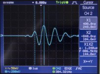
To answer your question first, Amp B RE picture ('Triangular)
This is with the Amp I term 'B' connected to the Earthed Ripple eater and output to the 8 ohm dummy load (with associated WW resistor inductance). Probe at x1 across the amp outputs.
Removing the RE earth the output reverts to pure sinusoidal.
When I switched on the amp today (no load) the output jumped back up as per AMP B with RE earth(ed) picture. About 250 mV P/P waveform (as against the low value yesterday). Nothing had been changed.
To keep it short, adding a 100 nF cap across the 2 secondary 25V AC ~ lines at the fuse block drops the waveform such that the RMS voltage is < 1 mV (1uS timebase) with or without the ground earth connection to the RE (slightly better with the earth connected). 25V~ to 0V also works but not as well (did not test both ~25V lines to 0V with 2 caps yet).
Ultimately the problem seems to be prior to the RE so I'll work on the transformer side first, before going back to actually loading the output, and see how it can be improved to stabilise the amp output voltage (i.e. such that this waveform is minimised)
BTW, I had checked the cap bank and RE previously without any amps connected and the waveforms were < 1.5 mV RMS.
Thanks for your patience and apologies dragging you into something that appears to be transformer related now.
Attachments

No, thank you for sharing.
I could be wrong, but it might be you are getting this ringing as the diode turns off. The diode OFF capacitance rings with the transformer leakage inductance. The issue arises (I'm simplifying here - others will explain it better) because as the diode switches off, it essentially 'kicks' the tank circuit formed by the leakage inductance and the diode OFF capacitance so it rings at HF. You will see little HF oscillation bursts repeating at 2x your mains frequency - so 100 Hz where you are.
It could of course be that some other piece of equipment is causing this. Because the bursts are at HF, they couple straight across the average mains transformer where the pri-secondary capacitance is typically 500pf-1500pf (I've measured this BTW on some toroidal transformers)
If this issue is arising on your amplifier rectifier, you can fix this by wiring a snubber in using 0.1 uF (film) capacitor in series with a 10-22 Ohm resistor right across the AC terminals of the rectifier. Keep the lead lengths as short as possible.
I posted some pics of my KX build here, for those interested:
https://www.diyaudio.com/forums/solid-state/96192-post-solid-pics-700.html#post6518937
https://www.diyaudio.com/forums/solid-state/96192-post-solid-pics-700.html#post6518937
No, thank you for sharing.
I could be wrong, but it might be you are getting this ringing as the diode turns off. The diode OFF capacitance rings with the transformer leakage inductance. The issue arises (I'm simplifying here - others will explain it better) because as the diode switches off, it essentially 'kicks' the tank circuit formed by the leakage inductance and the diode OFF capacitance so it rings at HF. You will see little HF oscillation bursts repeating at 2x your mains frequency - so 100 Hz where you are.
It could of course be that some other piece of equipment is causing this. Because the bursts are at HF, they couple straight across the average mains transformer where the pri-secondary capacitance is typically 500pf-1500pf (I've measured this BTW on some toroidal transformers)
If this issue is arising on your amplifier rectifier, you can fix this by wiring a snubber in using 0.1 uF (film) capacitor in series with a 10-22 Ohm resistor right across the AC terminals of the rectifier. Keep the lead lengths as short as possible.
Hi Bonsai,
Many thanks once again for your reply.
It certainly seems that the damped oscillation is due to the interaction between the diodes and the transformer inductance. I found an article on Rod Elliott's site on "Snubbers for PSUs" which goes into quite a lot of detail. Have not had this problem before and it seems that my case is 'extreme' but this is the first time with this particular transformer. Rod believes that this 'interference' is not audible anyway (although I'm aware some say it is).
Using a ground lift with 100nf/10R resistor across 2 back to back diodes at the transformer side reduces the amplitude by a factor of 2 to 3 without any diode bridge snubbers.
Whether this damped oscillation really matters or not I'm going to be pedantic and do my best to eradicate it as best I can and let you know my final, earthed, PSU setup before I move onto the final act of testing the amp and listening tests.
BTW,
I guess it's better to apply the snubbers directly to the RE bridge rectifiers themselves rather than at the transformer side? Reminder that the transformer secondary wires are split at the fuse boxes which separately feed the 2 Ripple eaters around 20cm or so away. I cut put the snubbers at the fuse boxes instead (in which case I'd just use one pair).
Cheers
I don't think it should matter much where the snubber is, I sometimes put that right on the transformer terminals, and that worked well too.
"I guess it's better to apply the snubbers directly to the RE bridge rectifiers themselves rather than at the transformer side? Reminder that the transformer secondary wires are split at the fuse boxes which separately feed the 2 Ripple eaters around 20cm or so away. I cut put the snubbers at the fuse boxes instead (in which case I'd just use one pair)."
Its important that you apply the snubbers right across the diode bridge with short leads. Its all about keeping the loop area as small as possible - short leads and twisted. You want to do this because if you put it at the transformer side with long wires, the wires will be radiating that hash inside the housing. If you are worried about neatness, you can tuck the snubber under the RE board. What you are doing with the snubbers is softening the diode conduction cut-off by absorbing the charge stored in the diode as it goes into reverse bias. Its the diode reverse bias capacitance forming a tank circuit with the transformer leakage inductance that causes the ringing.
You may hear this as interference if you have an AM radio, or in a really bad case, as a buzz (100 Hz 'tick-tick-tick' sound) on your speakers.
(I will add a snubber on the PCB if I do an update to the RE)
Component count is minimized when you place one snubbing resistor across each transformer secondary winding (rather than each diode). With proper choice of resistor value, this reduces the "Q" of the RLC resonant circuit below 0.5 so that no oscillatory ringing is possible. Or as they said in my EE classes at uni, this increases the damping "zeta" of the resonant circuit above critical-damping (zeta=1.0), so that no oscillatory ringing is possible.
The resistor does all the work of "killing the Q". The only purpose of the series capacitor is to decrease the amount of power dissipated in the resistor. Since, after all, the resistor is DIRECTLY ACROSS the secondary winding. You want the impedance of the capacitor to be very very low at the ringing frequency (> 100 kHz) so it doesn't interfere with damping. You also want the impedance of the capacitor to be very very high at the mains frequency (55 Hertz) so that very little current flows in the series RC circuit and heats up the resistor. A good compromise choice for the series C is 0.15 microfarads (150 nanofarads). At 55 Hertz its impedance is 19Kohms and at 100 kHz its impedance is 11 ohms.
_
Last edited:
Thanks for that Mark. The snubber I am proposing is in fact across the secondary winding but located at the bridge rectifier. I am no expert in this, so your input is appreciated.
I think you offered a snubber test jig some years ago? Maybe you can post a link so builders here can take a look.
I think you offered a snubber test jig some years ago? Maybe you can post a link so builders here can take a look.
Readers here might be more interested in the "principles of operation" document (link to pdf) than anything else.
It is stored here on diyAudio, as an attachment to post #1 of the following discussion thread"
Simple, no-math transformer snubber using Quasimodo test-jig
It is stored here on diyAudio, as an attachment to post #1 of the following discussion thread"
Simple, no-math transformer snubber using Quasimodo test-jig
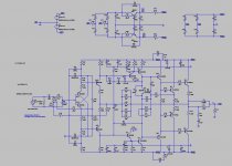
I just thought I would post a schematic of my complete setup (well, it does not include the transformers and soft start), this seems to work well too, with ripple eaters only for the front ends.
Please comment if you see potential issues/improvements.
Soft start is really simple: series resistor (6,8ohm 10W) on primary, and a relay to bypass it. Relay coil is connected via zeners to the rails at the smoothing caps, so the relay bypasses the resistor when the caps are charged to a voltage set by the zeners.
Attachments
I just thought I would add something that might be useful for other builders: I measured noise while swapping polarity on the primary on the transformer for one channel, and I could see a decrease in noise depending on that. This is with the amp connected to a source, with the signal grounds of both mono amps connected. My theory is that there are small common mode leakage currents in the transformers, and these current will flow through the signal ground via the source and create some noise. With the leakage current in opposite phase, the current will be higher, so matching the phase decreased the noise. Even when measuring the AC voltage between signal grounds with nothing connected, I could read 2,7V with the 'wrong' polarity, and 0,7V with the 'correct' polarity(less noise with source connected). Noise voltage at the output is in the 1mV range, with one primary polarity, and 2mV with the other.
Good tip! The reason is when the transformers are wired out of phase, you are in effect injecting a 300V peak signal between the primaries which couples through to the secondaries through the series pri-sec capacitance (typically 500 pF for a 500 VA toroid).
Good tip! The reason is when the transformers are wired out of phase, you are in effect injecting a 300V peak signal between the primaries which couples through to the secondaries through the series pri-sec capacitance (typically 500 pF for a 500 VA toroid).
The pri-sec capacitance can be almost 100% eliminated with foil screening between the windings. I use this technology, and the output wire of the foil is connected to the protective grounding.
Sajti
These transformers actually have the foil (Toroidy audio transformers), and it is conected to ground. I imagine it would have been worse without it.
I always specify an interwinding screen and a GOSS band on custom transformers. For a little additional expense its worth it.
A screen on a 1200VA toroid reduced the interwinding capacitance from 1.3nF to <100 pF. So, very big reduction, but still enough to couple some noise into your circuits. The common mode bandwidth on a toroid is >> 3 MHz - which stands to reason of course because its just a capacitor. Series mode typically 50-60 kHz.
For measurements and model, see slides 26-28 of the 'Ground Loops' presentation - link in my signature below.
(NB - the 500pF figure I mentioned in my earlier post is with the interwinding screen disconnected - its about 80pF when the screen is operational)
Last edited:
Bonsai, I think you need to include capacitor C3 in your amplifier and in your analysis.
C1 and C2 are the transformer's interwinding capacitances (with or without screen). C3 is an explicit discrete capacitor chosen by you and soldered to your circuit board. Quasimodo's design note makes a recommendation about selecting C3.
Notice that C3 forms a capacitive divider with C1 and C2, and so the RFI AC voltage on the secondary is less than the RFI voltage on the primary; its voltage is divided ... just as DC voltages are divided by a resistive divider. The ratio is:
{remember that impedance is inversely proportional to capacitance!}
If you choose C3 >>> C1+C2 then the denominator is enormously bigger than the numerator, and the RFI attenuation is also enormous. You get extremely little RFI on the secondary without an interwinding screen, and you get (extremely squared) RFI on the secondary with an interwinding screen. Benefit = high, cost = low, decision = easy.
_
C1 and C2 are the transformer's interwinding capacitances (with or without screen). C3 is an explicit discrete capacitor chosen by you and soldered to your circuit board. Quasimodo's design note makes a recommendation about selecting C3.
Notice that C3 forms a capacitive divider with C1 and C2, and so the RFI AC voltage on the secondary is less than the RFI voltage on the primary; its voltage is divided ... just as DC voltages are divided by a resistive divider. The ratio is:
- Vrfi_secondary = Vrfi_primary * ((C2 + C2) / (C1 + C2 + C3))
{remember that impedance is inversely proportional to capacitance!}
If you choose C3 >>> C1+C2 then the denominator is enormously bigger than the numerator, and the RFI attenuation is also enormous. You get extremely little RFI on the secondary without an interwinding screen, and you get (extremely squared) RFI on the secondary with an interwinding screen. Benefit = high, cost = low, decision = easy.
_
Attachments
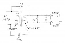
Mark, the model on page 28 of the Ground Loops presentation is just to demonstrate the change in pri-sec capacitance with a screen - not a real world model which would look a bit different (I will however add that to the presentation since it looks like this can be misconstrued).
For common mode noise, the secondary reservoir capacitance plays little part. The danger here is the noise crossing the pri-sec capacitance ends up in the interconnect signal returns between 2 pieces of gear, which means they are then in series with the signal voltage. The higher the freq, the worse the problem.
For series mode noise, the the reservoir capacitance is there and acts as an attenuator. However, once noise (primarily HF) in the housing it is radiated to surrounding circuits- at HF capacitively coupled and at LF magnetically. For this reason, if builders are serious about series mode line conducted noise, a filter has to be right at the mains input and enclosed in a metal can. You can buy very good IEC inlets with this function integrated from Schurter and Schaffer.
- Home
- Amplifiers
- Solid State
- Hifisonix kx-Amplifier